International Journal of Scientific & Engineering Research, Volume 4, Issue Ş, 2013 64
ISSN 2229-5518


—————————— ——————————

HE initial tension in a bolt after it has been installed is termed "preload" or ―pretension‖. Bolts must be in- stalled to a minimum level of preload, usually ex- pressed (in United States) as kips, or thousands of pounds. An ASTM A 325 bolt 7/8‖ diameter, for example, is to be pre- loaded to 39 kips, or more. There is no upper limit to this spe-
cified preload, only a lower limit. [1]
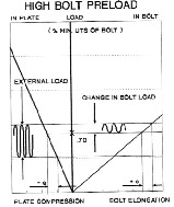
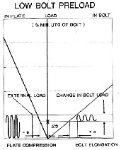
If a bolt has been preloaded to over 70% of the mini- mum specified ultimate tension for it's grade, as external load is applied to a connection, the bolt show only a change in tension which is a fraction of the external load. (Figure 1) The fraction seen is determined by the relative stiffness’s of the bolt vs. steel plate connection. Conversely, (as in Figure 2), if a bolt has been preloaded only to a low value, the same external load fluctuation will produce a tension change in the bolt which is relatively higher com- pared to the initial preload
. 

————————————————
Bipinkumar Kaswala pursuing masters degree program in Mechanical
Engineering Machine Dsign in RK University, India, PH-091
9998878460. E-mail: kaswala_bipin@yahoo.com
Prof.Keyur Hirpara currently Assist.professor in Department of mechani-
cal engineering in RK University, India, PH-091 9879519312. E-mail:
keyur.hirpara@rku.ac.in
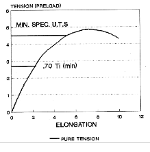
Figure 3 shows the typical tension/elongation curve for an ASTM A 235 bolt loaded in pure tension. The specified min- imum preload is 70% of the minimum specified ultimate strength (UTS) of the bolt, which is the highest point on its tension/elongation curve. Most high strength bolts have a minimum UTS somewhat higher than their specified minimum.

(mm)
J. M. Stallings and D.Y.Hwang [2] has contributed about the modeling of pretension in bolted connections based on finite element analysis approach. The pretensions are modeled by

http://www.ijser.org
65
International Journal of Scientific & Engineering Research Volume 4, Issue Şǰȱ ȱŘŖŗř

using temperature changes in the bolts. The methods pre- sented provide a direct means of calculating the magni- tudes of the temperature changes necessary to produce the desired pretensions without the use of trial and error or iterative methods. In the methods presented below, the ap- propriate temperature changes are calculated from the re- sults of one initial analysis of the connection. The methods apply to connections of arbitrary shape with one or more bolts. The magnitude of pretension can vary from bolt to bolt. The methods presented are also applicable to other systems such as post-tensioned concrete structures where an initial level of tension force is specified. The bolt is installed in the connection at a specified pretension. During installation, the connected material shortens as the pretension is applied. Equivalent stress conditions will be created in the bolt and the connected material if the bolt is installed without pre- tension, and the temperature of the bolt is then decreased.
Toney K. Jack[3] study on fastening bolt connection which are weakest link in integral engineering equipment, bolted joint connections require proper attention and detailed analysis at
Tension load in bolt:
Fp (Yp Fext ) PL
Maximum tensile stress in bolt in service

Fp ts
b
Compressive load induced in member
Fcl Ym Fext PL
Minimum Preload to prevent loss in compression
PL min Ym Fext
Equivalent Stress in Shank section
(5)
(6)
(7)
(8)
the design stage for a fail safe operation in service. The
yp
analysis is often lengthy with several variables under considera- tion. He has given a step-by-step guide; together with all re- quired equations for evaluating a typical bolted joint connection is given. A computer programmed solution in Microsoft Excel
eqv.

ts
Ks
e
b
(9)
TM for such analysis is shown through a worked example. The

yp eqv. ts t
b
(10)
author recommends a preload value of 70% - 80% of the static
tensile strength. This for a safer condition is best taken as the yield strength of the bolt material. because of the straight line relationship between increasing tensile load and bolt stretch up to the yield point of the bolt, a bolt torque tightened within its yield strength will be capable of developing the full rated tensile strength when subjected to additional load in excess of the preload. P Thus,
e
Stress concentration factors, Ks, Kt, are available as per material parameter. Area reduction or transitions such as bolt head fillet or chamfer, the start of the first thread and fillets in the plane of the nut are points of stress concentration.
Factor of safety for bending/fatigue: Fatigue assessment is based on the Soderberg criterion and the calculation of a safety factor or reliability index based on fatigue is:
PL y yp As
(1)

n yp
eqv.
(11)
Tension Load or tensile stress induced in bolt body (with tigh-
tening torque):
PL

bt A (2)
b
changing the preload value through altering the preload-to- yield factor, significantly influences the degree of reliability of the joint. The question of an adequate preload is thus best answered by conducting a what-if type analysis with the pro- gram
Torsional Shear Stress:

16T
D3
(3)
Design check for Fatigue loading condition: Bolt working load or equivalent stress ≤ load at yield point.
N. Ganji [4] gives a thought about the joint connector in which it is necessary that the joint is fastended with a perticular ten- sion.If the fastener pretension is too tight, it may cause damage

Principal Stress or Working Stress in bolt
2
to the structure or the fastened itself might break.On the other hand, if the applied pretension is too less, it might result in ex-
bt
bt
2
(4)
cessive vibration of the structure or unnecessary leaks.So, it is

1 2 2
necessary that the fastener is tightened with appropriate ten- sion. The author has define the procedure for the pretension

http://www.ijser.org
66
International Journal of Scientific & Engineering Research Volume 4, Issue Şǰȱ ȱŘŖŗř

method using ABAQUS software .The pretension surface has been define in finite element model for applying tension force.The surface is chosen approximately at the center of the fastener shank.Once,the assembly load is prescribed,it is then applied to the pretension surface of the element to simulate the tension of the assembly. A pretension node which control the pretension section should be defined.The pretension node is mainly used to apply load preload across the pretension sec- tion and maintain the tightening adjustment so that the load across the fastener may increses or decrease upon loading of the structure.This node hase only one degree of freedom. A point load is applied to the pretension node representing the torque applied to the fastener.This load acts in the direstion of normal on the part of the fastenet underlying the pretension section.The total force transmitted across pretension is the combination of reaction force at pretension node and any concentrated load at the node
H. CELIK explain [5] the study about, advanced computer aided engineering (CAE) methodologies, has been applied as method of solution. The stress distributions has been identify on the preloaded bolt connections using advanced CAE applications. The simulation and the stress distributions of the bolt-nut couples were determined through finite element analysis (FEA) with non-linear contact definitions using a commercially availa- ble FEA code. Simulation results showed that even though par- tial stress accumulations were seen on the bolts, these would not cause any plastic deformation or failure. For the final evalu- ation, safety factors of the fasteners were calculated according to the material yield point
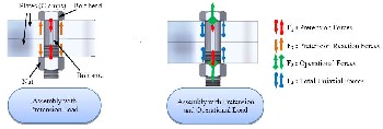

Author has also discussed about the pretension triangle in uniaxial loading casewith in the elastic deformation limit, the triangle defines the relationship between forces, deformation existing on the plates/clamps and bolt, it is also known as Rot- scher pretension triangle diagrams.
G.Dinger and C. Friedrich[6] talked about a numerical design
Y. SHOJI [7] said the pretension load of each bolt is applied us- ing the special ―bolt-pretension‖ capability of the program and the bolt length is "fixed" after tightening so that the changes of the bolt-tension can be captured. The material properties used in the analyses are such as: Young’s Modulus (E), Poisson’s Ra- tio(ν )
The Constraints (Boundary conditions) (a) and (b) were consi- dered to model different nut conditions: (a) Nut is allowed to rotate about its axis that is collocated to the bolt axis. Bolt top is allowed to move only in the radial (x-) direction. This is the case of "normal" situation. (b) Nut is allowed to rotate about its axis that is collocated to the bolt axis. Bolt top is allowed to move only in one radial (x-) direction, and the bottom is constrained not to move in the radial directions (x- and y-directions). This is the case of the first nut of "double nut" situation, or ―con- strained‖ situation. (c) After the pretension, nut is moved to the radial direction and in perpendicular to the bolt motion (z- direction) in order to "lock" the bolt by plunging nut thread into bolt thread.
To check the variation effect of the pretension loads, the author has considered different loadcases.The result of lateral dis- placement has been obtained. This means that the bolts are not loosened easily, if a certain preload is applied, or the bolts are tightened adequately
T.N.Chakherlou experimental results[8] shows that the bolted joint specimens, for which the fastener hole contains edge cracks, have a greater fracture strength than those which lack a bolt which would be the situation had in practice there been a bolt but very lightly tightened. it was found that the greater the bolt tightening torque, the greater the resultant fracture strength.


The paper present to idea about the bolt pretension of deep tillage equipment.this study is further discussion of the the au- thor discuss earlier [5].but , he has not given any idea about how force calculated and soil condition. In this study that has been explain.The factor of safety has been identify for the bolt – nut connector used in tillage tool. The material used in the study as shown below

method with finite element analysis for detecting and under- :
standing of the self-loosening process at bolted joints and the influences of the preload generation for the residual shank tor- que in the numerical simulation. Fatigue and rotational self- loosening are the two most widespread reasons of failures dur- ing operation. Whereas the mechanism for failure in fatigue or preload relaxation of a bolted joint can be analysed with the help of analytic guidelines and design tools, no established and
verified design method exists in case of preload loss caused by
rotational self-loosening of the screw. A three-dimensional finite element (FE) model is established for detection and understand- ing of self-loosening at bolted joints and the influences of the preload generation for the residual shank torque
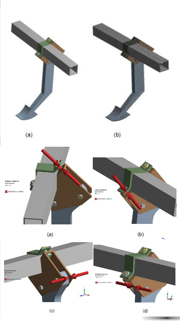
The Poisson ratio has been taken 0.3. In the simulation study, the chisel tine bolt group is defined with four metric 8.8 proper- ty class bolt nut fasteners (in two are M20, two are M16). AN- SYS Workbench commercial Finite Element code was utilized for the FEA with geometrical and face to face contact non-

http://www.ijser.org
International Journal of Scientific & Engineering Research Volume 4, Şǰȱ

linearity assumptions. Bolt teeth were ignored for geometrical simplification operations and nuts are defined to bolt with bonded contact assumptions. Friction coefficient between all parts is assigned as 0.12
The further study has been covered on deep tillage tools used in agriculture, which experience high level soil reaction forces dur- ing tillage operations. These forces may cause plastic deforma- tion or failure which is undesirable for tillage machines/tools. In particular, fasteners such as bolt connections, which are uti- lized in the fastening of structural elements to the tillage tool’s framework, may become a key point for possible machine fail- ure during tillage operations. Therefore, prediction of the stress distribution or likely failure point of the bolt connections during tillage operations is a very significant issue.
The soil is compaction occurs when a force compresses the soil and pushes air and water out of it so that it becomes denser. Compaction is more severe when the soil is wet and less able to withstand compression. Compaction is a concern because it affects plant growth. There are not enough pores or spaces in compacted soil to allow unrestricted root movement, infiltra- tion, drainage or air circulation. In this study, the focus is on the determination of the stress distributions on the preloaded bolt connections of a chisel tine.
The property of soil used for experiment
– Bulk density(Kg/m3)=1300
– Yield limit/pressure limit(KPa)=12.5
– Moisture content=13%
The teardown force 6500(N) has been calculated form the bulk density using volume of tool use for tearing.
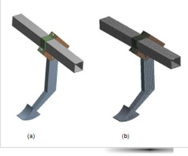
In this simulation following part need to model with use of CAE tool such as pro-e (Creo element).The bolt- nut fastener are made from standard data sheet of metric hexagon bolts.Other part such as chisel leg and tine are available standard in market in much variety, which dimension given by customer
67
The actual capacity of preload of bolt material is higher, but the Value has been decide on the basis of geometry complexity and shape which show the non linear deformation.


Actual Capacity of Preload 145000N for M20 Bolt and Actual
Capacity of Preload 95000N for M16 Bolt.
(1) Case 1
The pre load has been set 40,000 N for M20 Bolts and 37,000 N
for M16 Bolts. External Ploughing force 6500 N has been calcu-
lated from the soil bulk density and contact area of the chisel
tool.

http://www.ijser.org
68
International Journal of Scientific & Engineering Research Volume 4, Issue Şǰȱ ȱŘŖŗř

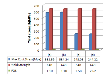
The chart illustrate, that the factor of safety obtain from the result is minimum than the allowable limit for bolt (c ) and (d),if safety factor consider two.
(2) Case 2
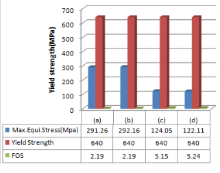
Again the Preload has been set 20000 N for M20 Bolts and
18500 N for M16 Bolts. External ploughing force 6500 N has
been applied.
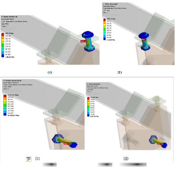
Plot illustrare, the bolt connection which are in safer with con- sidered preload value for this case.In addition, the safety fac- tor has been comes more than two value for all four bolt con- nection as shown in Figure 10.


The Numerical results show that the bolted joint specimens, for
1st case the factor of safety (Figure 8) comes are higher than the
allowable limit if considering factor of safety 2.
If consider 2nd case which give factor of safety more than 2
(Figure 10) which have a greater fracture strength than those
which lack a bolt which would be the situation had in practice
there been a bolt but very lightly tightened. Indeed, it was found that the greater the bolt tightening torque, the greater the
resultant fracture strength, as can be seen from 1st case. The FE results also support this finding as the stress intensity factor for the bolted specimens was found to be consistently lower than for the bolt-less hole specimen and with a similar relative differ- ence. The experimental results also show that the fracture strength reduced significantly with increased stress concentra- tion length and that the relative improvement resulting from bolt clamping was realized across a wide range of stress concen- tration lengths. This finding is also supported by the FE results
as the stress intensity factor was found to be greater for larger stress concentration for all the specimen variants considered


The FE analysis has shown that for a given applied tensile stress, the equivalent stress on the bolt joint is lower compared with a bolt-less hole containing similar edge cracks. This is due to the normal stress and friction force (stress) between contact- ing surface of bolt head (or nut) and plate which acts as a resis- tant force against external applied tensile load and reduces the stress (caused by external load) around the hole and crack tip.
The methodology has been very usefull to reduce the cost of component to know it actual bavaviour before the prototype. In addition,there are some other method also has been available, but it need some instrument and physical condition.This type of numerical base technique only need physical property and pa-

http://www.ijser.org
69
International Journal of Scientific & Engineering Research Volume 4, Issue Şǰȱ ȱŘŖŗř

rametric geometry with load condition which make fast evalua- tion time.

As | Tensile Stress Area, mm2 |
Ab | Cross-Sectional area of body, mm2 |
D | Nominal Bolt Diameter, mm |
Ds | Body Diameter, mm |
E | Elastic Modulus, N/mm2 |
Fext | External Load, N |
Kb | Stiffness of Bolt, N/mm |
Km | Stiffness of Clamped member, N/mm |
Kt | Stress Concentration factor for Thread |
Ks | Clamping or Grip Length, mm |
M | Bending Moment, Nm |
PL | Nominal Preload, N |
T | Tightening Torque, Nm |
Y | Preload-Yield factor |
Yb | Stiffness Parameter of Bolt |
Ym | Stiffness Parameter of Clamped Member |
α | Coefficient of thermal expansion |
L | Original length mm |
Greek Letter
citation)
[5] H. CELIK, "Non-Linear Stress Analysis for the Bolt Connections of A Chisel using finite element method" AKdniz University,Faculty of Agriculture,Department of agricultural Machinery,Antalya,Turkey-
2012.(Technical paper)
[6] G.Dinger, C. Friedrich: "Avoiding self-loosening failure of bolted joints with numerical assessment of local contact state," engineering Failure Analysis , vol. 18, pp. 2188-2200, 2011(Journal or magazine ci- tation)
[7] Y. SHOJI, "ANALYTICAL RESEARCH ON MECHANISM OF BOLT LOOSENING DUE TO LATERAL LOADS," in ASME pressure vessels and piping division conference, Denver,Colorado ,USA, 2005. (Conference proceedings)
[8] T.N.Chakherlou, "The effect of bolt clamping force on the fracture strength and the stress intnsity factor of a plate containing a fastener hole with edge cracks," Engineering Failure Analysis, vol. 16, pp. 242-
253, 2009. (Journal or magazine citation)
[9] Fastenal industrial and construction supplies, "Technical reference
Guide," 2012. [Online].
Available: http://www.fastenal.com/web/en/69/bolted-joint- design;jsessionid=g. [Accessed 03. 12. 2012]. (Technical report with report number)
[10] G. L. Kulak, "Field study of bolt pretension," Journal of construction
steel research, vol. 25, pp. 95-106, 1993. (Journal or magazine citation) [11] Bolt Grade Markings and Strength Chart[online]. http://k- tbolt.com/bolt_chart.htm [Accessed 03. 12. 2012]. (URL for
Transaction, journal, or magzine)
[12] Proof Load Tensil Strength For Grade 2, 5, & 8. [online] http://www.almabolt.com/pages/catalog/bolts/proofloadtensile.ht m. [Accessed 03. 12. 2012]. (URL for Transaction, journal, or magzine)
[13] Protect your soil from compaction,NSW Department of Primary
Industries[online] http://www.dpi.nsw.gov.au/Agriculture
/resources/soils/structure/compaction [Accessed 03. 12. 2012] (URL
for Transaction, journal, or magzine)

[1] Heavy Movable structural Movable Brideges affiliate," American consulting engineer’s council's, 12-15 November 1990. [Online]. [Ac- cessed 25. 02 .2013]. (Technical report or magazine citation)
[2] J. M. Stallings, D.Y.Hwang, "Modeling pretensions in bolted connec- tions," Computer & Structure, vol. 45, no. 4, pp. 801-803, 1992(Journal or magazine citation)
[3] Toney K.Jack, "A Method for the Stress and Fatigue Analysis of
bolted joint connections:together with programmed solution," Inter- national Journal of engineering and advanced technology, vol. 1, no.
3, 2012(Journal or magazine citation)
[4] N. Ganji, "Parametric study of load transfer two-bolted signal hybrid (bonded/bolted)sear joint," Department of mechanical engineer- ing,wichita state university, Hyderabad, 2001. (Journal or magazine

http://www.ijser.org