International Journal of Scientific & Engineering Research, Volume 3, Issue 11, November-2012 1
ISSN 2229-5518
A Review and Analysis of Motion Sensor System
Applications for Human
Pawan Kumar, Meenu Bhardwaj
Abstract— Wearable motion sensors consisting of accelerometers, gyroscopes and magnetic sensors are readily available nowadays. The small size and low production costs of motion sensors make them a very good tool for human motions analysis. This paper presents the design of a wireless sensor system developed using a Microchip PICDEM developer kit to acquire and monitor human heart sounds for phonocardiography applications. With their lower cost and increased intelligence, man-made motion sensors are expected to play an increasingly important role in biomedical systems for basic research as well as clinical diagnostics.
Index Terms— accelerometers, gyroscopes, motion sensors, phonocardiography.
—————————— ——————————
1 INTRODUCTION
OTION sensing plays an important role in medical practice. For example, rotation of head and orientation of body are the input signals for human prosthesis; the
movement of chest wall needs to be precisely monitored when a ventilation machine is used to support human breath, the body motion characteristics also need to be evaluated during the rehabilitation process of disabled people. Recently, mi- croscale motion sensing technologies have gained great ad- vances, which helped in the development of human prosthe- sis, sports medicine, radiotherapy, and biomechanical re- search. Micro-electro-mechanical-systems (MEMS) with high accuracy, high reliability and multiple functionalities has pro- vided a powerful tool set for body motion sensing.
Wearable inertial motion sensors consisting of accelerometers,
gyroscopes and magnetic sensors are easily available nowa-
days. Many companies, such as XSens Technologies (The
Netherlands) and Innalabs (Russia) provide inertial motion sensor solutions. Data from accelerometers and gyroscope
could be used to estimate orientation relative to an inertial frame. Although relative orientation could be estimated by integration of data from gyroscope, errors would accumulate by this method, which caused distortion and drift errors.
2 HUMAN BALANCING SYSTEM
The vestibular system is the best example, which contributes to balance in most mammals and to the sense of spatial orien- tation, is the sensory system that provides the leading contri- bution about movement and sense of balance. Together with the cochlea, a part of the auditory system, it constitutes the labyrinth of the inner ear in most mammals, situated in the
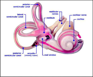
vestibulum in the inner ear (Figure 1). As movements consist of rotations and translations, the vestibular system comprises two components: the semicircular canal system, which indi- cates rotational movements; and the otoliths, which indicate linear accelerations. The vestibular system sends signals pri- marily to the neural structures that control eye movements, and to the muscles that keep a creature upright. The projec- tions to the former provide the anatomical basis of the ves- tibulo-ocular reflex, which is required for clear vision; and the projections to the muscles that control posture are necessary to keep a creature upright. The semicircular canals are in charge of rotational movement sensing, while the otoliths are in charge of translational movement sensing. The semicircular canals are filled with a body fluid, named endolymph, which moves relatively to the canal wall when the subject experienc- e
Fig. 1. Human vestibular inner ear
————————————————
Pawan Kumar is Lecturer Department of Electronics and Communication engineering in Guru Tegh Bahadur Institute of Technology , New Del- hi,India PH-+91 8285542655. E-mail: pawan1234@gmail.com.
Meenu Bhardwaj is currently pursuing masters degree program in VLSI Design engineering in Banasthali Vidyapith University, India, PH-+91
9811991276. E-mail: menu.bhardwaj1908@gmail.com.
Since the vestibular system is an indispensable part of the hu- man balance system, its disorder causes a range of symptoms including blurred vision, vertigo, chronic dizziness, and in- creased fall risk. Vestibular disorder is caused by various rea- sons, like injury, infection, neural diseases, surgery, drug poi- soning, etc., pharmaceutical treatments alone are ineffective for their treatment. Nowadays, many man-made motion sen- sors with the functions comparable to that of the vestibular
IJSER © 2012
http://www.ijser.org
International Journal of Scientific & Engineering Research, Volume 3, Issue 11, November-2012 2
ISSN 2229-5518
system have been developed.
3 TYPES OF MOTION SENSORS
Type of sensors used ranged from uniaxial accelerometers to triaxial accelerometers, gyroscopes and magnetic sensor. Full scale of accelerometers ranged from 3 g to 10 g, those of gyro- scope ranged from 300–1,200 degree/second. The weight of motion sensors adopted ranged from 18.2 g to 700 g, and the size ranged from 20 × 10 × 7.2 mm3 to 64 × 62 × 26 mm3. Sampling frequencies of these systems ranged from 20–800
Hz.
3.1 Cantilever Based Accelerometers
Earlier the devices were somewhat unreliable, large and ex- pensive. Due to advancement of microfabrication technolo- gies, state-of-the-art micro-accelerometers have become more accurate, reliable, smaller and cost effective. Besides the bandwidth ,the most important property of an accelerometer is its sensitivity S For a piezoresisitive of an accelerometer S is defined as the relative change of resistance per unit of acceler- ation a
S = ARjRa (2)
The change of resistance is proportional to the elastic strain E
at the site of the resistor
AR/R = KE
A typical cantilever based accelerometer structure can be rep-
resented by a mass-spring-damper system. The inertial force generates a relative movement between the proof mass and
the supporting frame, and induces mechanical stress within the cantilever. Both of the relative movement and the mechan- ical stress can indicate the external acceleration.
3.2 Capacitive Accelerometer
Capacitive accelerometers (vibration sensors) sense a change in electrical capacitance, with respect to acceleration, to vary the output of an energized circuit.
The sensing element consists of two parallel plate capaci- tors acting in a differential mode. These capacitors operate in a bridge circuit, along with two fixed capacitors, and alter the peak voltage generated by an oscillator when the structure undergoes acceleration. Detection circuits capture the peak voltage, which is then fed to a summing amplifier that processes the final output signal. Capacitive accelerometers sense a change in electrical ca- pacitance, with respect to acceleration, to vary the output of an energized circuit. When subject to a fixed or constant acceleration, the capacitance value is also a constant, resulting in a measure- ment signal proportional to uniform acceleration, also referred to as DC or static acceleration.
PCB’s capacitive accelerometers are structured with a diaphragm, which acts as a mass that undergoes flexure in the presence of acceleration. Two fixed plates sandwich the diaphragm, creating two capacitors, each with an individual fixed plate and each shar- ing the diaphragm as a movable plate. The flexure causes a capac- itance shift by altering the distance between two parallel plates, the diaphragm itself being one of the plates. The two capacitance values are utilized in a bridge circuit, the electrical output of which varies with input acceleration.
3.3 Piezoresisitive and Piezoelectric Accelerometers
The configuration of the cantilever structures in piezoresisitive accelerometers is similar to those in capacitive accelerometers, while their electrical measuring mechanisms are different. The implantation of a piezoresisitive material on the upper surface of the flexural element was used for measuring out-of-plane acceleration of the proof mass. The strain experienced by a piezoresisitive material causes a position change of its internal atoms, resulting in the change of its electrical resistance. By completing a Wheatstone bridge around the piezoresistors of the accelerometer, a linear relationship between acceleration and voltage can be derived.
To maximize sensor sensitivity, the flexural width w is mini- mized while the radial length r of the proof mass is maxim- ized. The bandwidth of the accelerometer is determined from the length of the flexure l, with shorter flexural elements in- creasing the lateral resonant frequency of the sensor.
3.4 Gyroscopes
A gyroscope is a device for measuring or maintaining orientation, based on the principles of angular momentum .Mechanically, a gyroscope is a spinning wheel or disk in which the axle is free to assume any orientation. Although this orientation does not re- main fixed, it changes in response to an external torque much less and in a different direction than it would without the large angu- lar momentum associated with the disk's high rate of spin and moment of inertia. Since external torque is minimized by mount- ing the device in gimbals, its orientation remains nearly fixed, regardless of any motion of the platform on which it is mounted. Gyroscopes based on other operating principles also exist, such as the electronic, microchip-packaged MEMS gyroscope devices found in consumer electronic devices, solid-state ring lasers, fibre optic gyroscopes, and the extremely sensitive quantum gyro- scope.
Applications of gyroscopes include inertial navigation systems where magnetic compasses would not work or would not be pre- cise enough, or for the stabilization of flying vehicles like radio- controlled helicopters or unmanned aerial vehicles. Due to their precision, gyroscopes are also used to maintain direction in tun- nel mining.
The underlying physical principle of a vibrating structure gyro- scope is that a vibrating object tends to continue vibrating in the same plane as its support rotates. Vibrating structure gyroscopes are simpler and cheaper than conventional rotating gyroscopes of similar accuracy.
Consider two proof masses vibrating in plane (as in the MEMS


gyro) at frequency . Recall that the Coriolis effect induces an acceleration on the proof masses equal to  , where is a velocity and is an angular rate of rotation. The in-plane velocity

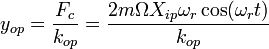
of the proof masses is given by: , if the in-plane position is given by . The out-of-plane motion , induced by rotation, is given by:
Where,

is a mass of the proof mass,
is a spring constant in the out of plane direction,
IJSER © 2012
http://www.ijser.org
International Journal of Scientific & Engineering Research, Volume 3, Issue 11, November-2012 3
ISSN 2229-5518

is a magnitude of a rotation vector in the plane of and perpendicular to the driven proof mass motion.
In application to axi-symmetric thin-walled structures like beams and shells, the Coriolis forces cause a precession of vibration pat- tern about the axis of rotation. For such shells, it causes a slow precession of a standing wave about this axis with an angular rate which differs from input one. It is so-called "wave inertia effect".
4 APPLICATIONS OF MOTION DETECTION
4.1 Phonocardiology
Acoustic monitoring of a heart condition by PCG is harmless and nonintrusive, the setup is lightweight, and a relatively low level of experience and skill is needed to set up the system and acquire the signals. The PCG recording requires only a single probe and does not use wires, the time to set up PCG recording is shorter, compared to ECG and MRI. More importantly, PCG offers the ability to quantitate the sounds made by the heart providing in- formation not readily available from more sophisticated tests. Recently Bluetooth-based wireless data acquisition system for Phonocardiogram and wireless medical stethoscopes are devel- oped. The advantage of using the Bluetooth protocol is that it allows a very high data rate compared to other protocols such as Zigbee and Wi-Fi. However, it requires high-performance micro- processors, which consumes high energy, have a shorter battery life, and tend to be somewhat expensive compared to Zigbee de- vices.
4.2 WSN Platforms and Phonocardiography Sensors
The WSN platforms can be categorized into three main groups, namely, Advanced RISC Machine (ARM)-based plat- forms, microcontroller-based platforms and RF integrated platforms. In applications where power consumption is a ma- jor issue, microcontroller-based platforms are considered much more suitable. The MicaZ platform is specifically opti- mized for low-power, battery-operated networks. This plat- form uses an ATmega processor, which is a comparatively slow processor but requires much less power than ARM pro- cessors. A wireless sensor system for PCG applications has two main keys: a wireless platform and a PCG sensor. The most common PCG sensor for medical applications is a stetho- scope.
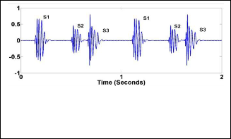
The aim of these sensors is to detect heart sound signals from the human body. The heart sound data is independently sam- pled using a microprocessor on a WSN platform at an appro- priate sampling rate to detect significant characteristics of the heart signal. Heart sounds lie in the frequency range between
20 Hz and 2 kHz.
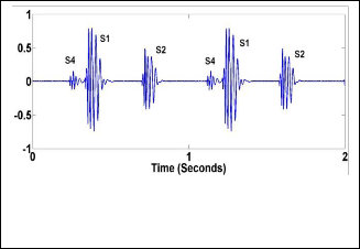
Fig. 3 . Abnormal Heart Sounds(S3).
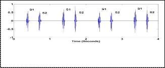
Fig. 4. Abnormal Heart Sounds(S4).
The most fundamental heart sounds are the first and second heart sounds (S1 and S2) as shown in figure. The abnormal heart sounds (S3 and S4) shown in Figure 4(a,b) are the sign of cardiovascular disorders, but also can sometimes be heard in healthy children and young adults. The frequency of heart sounds lies in the range of 20–200 Hz for S1 and S2, and less than 50 Hz for S3 and S4. Also, an extra or unusual sound, called a heart murmur, can be heard during a heartbeat. A heart murmur frequency lies anywhere between 20 Hz and 2 kHz.
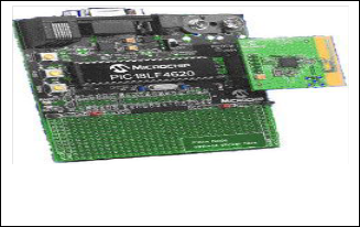
Fig. 2. Fundamental Heart Sounds (S1 and S2).
Fig. 5. Microchip, PICDEM Z development board
IJSER © 2012
http://www.ijser.org
International Journal of Scientific & Engineering Research, Volume 3, Issue 11, November-2012 4
ISSN 2229-5518
The platform is based on the “PICDEM’ developer kit from Microchip. Microchip processor PIC18F4620 and a Chipcon Zigbee CC2420 wireless transceiver radio are the main com- ponents.
TABLE 1
COMPARISION BETWEEN VARIOUS TECHNOLOGIES
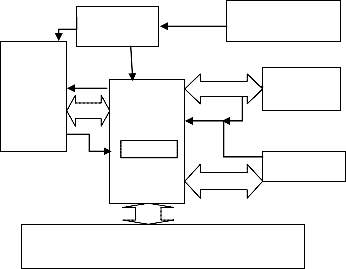
CHIP- CON ZIGBEE
VOLTAGE REGU- LATOR
MICROCHIP PIC18F4620
BATTERY
ACCELEROME- TER SENSOR
SPI
IP
SOUND SENSOR
HOST COMPUTER
EUSART
Fig. 6. Architecture of Wireless Sensor Platform.
The important section of this platform is PIC18F4620 micropro- cessor having features like include nanoWatt technology for low power operations, multiple oscillator options for operating at dif- ferent clock speeds, advanced memory management for increased programming flexibility, enhanced addressable USART, a 10-Bit A/D converter, and an extended watchdog timer. The processor’s maximum clock speed is 40 MHz and it is capable of sustaining 8
MIPS with a supply voltage of 5 V.
The processor has three programmable interrupt inputs, which allows to monitor three different signals simultaneously. We can use one of the interrupts for invoking the processor from sleep. The application software decides when to put the processor to sleep during which NanoWatt technology is invoked. As the processor is sleeping, the interrupt pin is the only active pin which can wake up the processor once it detects changes in the electrical signals on the pin. The ability to place the processor on standby is necessary to conserve battery power. The processor provides 13 channels for 10-bit analog to digital conversion (ADC). All of the A/D pins can be programmed as both input and output pins. Three pins can be programmed for multiplex with an alternate function from the peripheral features on the device.
Enhanced Universal Synchronous Asynchronous Receiver Transmitter (EUSART) module is also available in this processor. The EUSART provides more robust, reliable, and faster data transfers between two devices when compared to traditional UAR. The PIC18LF4620 provides seven operating power modes and hence may support more efficient power management. It supports direct memory addressing. Direct addressing allows the user to access any location in the processor’s main memory with- out a fixed address in the instructions.
5 CONCLUSION
This paper presents the design and testing of a wireless sensor system developed using a Microchip PICDEM developer kit to acquire and monitor human heart sounds for phonocardiography applications. The system can serve as a cost-effective option to recent developments in wireless phonocardiography sensors that have primarily focused on Bluetooth technology. In contrast to the solid-state sensors described in the paper, that have been widely used for body motion measurement, the applications of non solid-state motion sensors are still in the initial stage. The implementation of body motion sensing using liquid-state sensors or air based sensors is yet to come. This paper aims to cover the critical conventional sensing modalities as well as typical emerg- ing technologies which may play a leading role in the market of body motion sensing in the near future.
REFERENCES
[1] . Gong, W.; Merfeld, D.M. Prototype Neural Semicircular Canal Prosthesis
Using Patterned Electrical Stimulation. Ann. Biomed. Eng. 2000, 28, 572-581.
IJSER © 2012
http://www.ijser.org
International Journal of Scientific & Engineering Research, Volume 3, Issue 11, November-2012 5
ISSN 2229-5518
[2] Van der Kooij, H.; Jacobs, R.; Koopman, B.; Grootenboer, H. A multisensory
Integration Model of Human Stance Control. Biolog. Cybern. 1999, 80,
299-308.
[3] Carlos, E.D.; Kiran, S.D.; Julian, L.A. Chest Wall Motion before and during Mechanical Ventilation in Children with Neuromuscular Disease. Pediat. Pulm. 1993, 16, 89-95.
[4] Kim, S.; Pakzad, S.; Culler, D.; Demmel, J.; Fenves, G.; Glaser, S.;
Turon, M. Wireless Sensor Networks for Structural Health Monitor- ing. In Proceedings of the 4th International Conference on Embedded Net- worked Sensor Systems, Boulder, CO, USA, 31 October–3 November
2006;pp. 427–428.
[5] “A Xu, N.; Rangwala, S.; Chintalapudi, K.K.; Ganesan, D.; Broad, A.; Govindan, R.; Estrin, D.A wireless Sensor Network for Structural Monitoring. In Proceedings of the 2nd International Conference on Em- bedded Networked Sensor Systems, Baltimore, MD, USA, 2004; pp. 13–
24.
IJSER © 2012
http://www.ijser.org