International Journal of Scientific & Engineering Research Volume 4, Issue 1, January-2013 1
ISSN 2229-5518
A Methodology for Validation of OCL Constraints Using Coloured Petri Nets
Aakanksha Sharaff
Abstract— Unified Modelling Language is the standard language for modelling the software architecture of a large scale application system. It makes a blueprint for the construction of software design. The different UML diagrams such as use case diagrams, activity diagrams, class diagrams, state chart diagrams, sequence diagrams, collaboration diagrams etc. prove to be quite helpful in System Analysis and Design. The most important diagram i.e., UML class diagram addresses the static structure of the system. It defines the attributes and behavior (operations) of the class. UML class diagram provides the structural behavior of the system but at the same time precision and details are also required for proper System Analysis and Design. In order to achieve this precision and detail, constraints needs to be described. These constraints are invariants which are described by Object Constraint Language (OCL). OCL is a formal modelling language which is used with UML class diagram to model a system with a high abstraction level. These UML model associated with OCL needs to be verified to check whether it meets the user requirement or not. So, Coloured Petri Net (CPN) is used for model checking. CPN checks the dynamic behavior of the application. This paper develops a transformation approach to achieve precision and detail while modelling the behavior of the system. In order to describe this process, an example of Automatic Teller Machine (ATM) is illustrated.
Index Terms— Class Diagram, Coloured Petri Nets (CPN), Model Checking, Object Constraint Language (OCL), Personal Identification
Number (PIN), Unified Modelling Language (UML).
—————————— ——————————
1 INTRODUCTION
A model is an abstraction of something for the purpose of understanding it before building it [1]. Many kinds of models for various purposes are designed before developing the model. Unified Modelling Language provides a standard notation for developing these models. UML diagrams makes blueprint for the development of the system which simplifies the complex process involved in the system. UML diagrams provide both the structural views and behavioral views of the system. There are different UML diagrams such as use case diagrams, activity diagrams, class diagrams, state chart diagrams, sequence diagrams, collaboration diagrams, deployment diagrams etc. UML sequence diagram and collaboration diagram helps in designing real-time system. Out of these several UML diagrams, class diagram plays a very important role in developing the model. It helps in designing the static structure [18] of the system. UML class diagrams define the attributes and behavior (operations) of the class in the system. UML class diagram lacks in providing precision and unambiguous detail which are the relevant aspects of the specification. In order to achieve these aspects of specification, there is a need to describe the constraints. These constraints can be described using natural language but it still lacks unambiguous specification of the system. So, formal languages have been developed to write unambiguous specification of the system. Hence, Object Constraint Language (OCL) comes to fill this gap. OCL [3] is easy to write and is a pure expression language. OCL describes the constraints and these constraints can be specified as invariants, precondition and post-condition. OCL is not a programming language as a result it does not depict the program flow or flow of execution. It is a modelling language but not directly executable. To make UML-OCL model executable and to check whether it conforms the user requirement or not Coloured Petri Net (CPN) is used. CPN implements the dynamic
behavior of the system and is represented as a set of state and transition diagrams. CPN is a formal modelling language that models the graphical representation of the system and addresses the behavioral aspects of the system.
The main aim of this paper is to develop an unambiguous and precise UML-OCL model which can be executable and free from ambiguity. The goal of using CPN is to check the model as to whether it meets the customer requirement or not. To meet the customer requirements, the designer should understand the problem, reduce the potential errors, if any, caused by ambiguous requirement. The potential errors would be removed by decomposing the user requirement, specifying and modelling the system according to the functional requirement of the system. Hence, OCL-CPN combines to provide a generalized model of the system which is free from ambiguity.
The remaining portion of the paper is organized in the following manner. Section II describes the related concepts UML, Object Constraint Language, Coloured Petri Nets and CPN tool. Section III presents the Proposed Work. Section IV gives the CPN model of the proposed work along with its validation. Section V gives the conclusion and future work.
2 RELATED CONCEPTS
Unified Modelling Language is used in this paper to analyze and design the model, OCL is used to develop the model which is free from ambiguity and to check the model whether it conforms the user requirement or not, Coloured Petri Nets is used.
2.1 Unified Modelling Language
UML model is a simplification of reality [2]. We build models to better understand the system which we are developing. The
IJSER © 2013 http://www.ijser.org
International Journal of Scientific & Engineering Research Volume 4, Issue 1, January-2013 2
ISSN 2229-5518
UML models helps to visualize the system, specify the struc- ture and behavior of the system, gives the template to con- struct the system and document the artifacts of the system [2]. The UML offers several kinds of diagrams, dedicated to de- scribe different aspects of a system, such as structure, interac- tion, state based behaviour or deployment [2]. The UML in- corporates a language called Object Constraint Language that can be used for navigation [1].
2.2 Object Constraint Language
The Object Constraint Language (OCL) is a textual specifica- tion language, designed especially for the use in the context of diagrammatic specification languages such as the UML [3]. It defines preconditions, post-conditions and invariants as con- straints but it also requires the elements defined in UML dia- grams such as classes, attributes, methods etc. UML-OCL dia- gram allows preconditions and post-conditions to specify the methods (operations) of the classes. Its main purpose is to make UML models more precise by providing a constraint language [4]. For example, class diagrams can be precisely defined using OCL. The Object Constraint Language [3] was proposed as a way to bring additional precision to analyse or design models defined with the Unified Modeling Language. OCL brings precision to modeling activities and offers a num- ber of potential benefits [5, 6, 7]. The invariants are specified on
3 PROPOSED WORK
The system developer must analyze the different views of the system to build complex systems. Models should be built by using precise notations and should be verified to satisfy the requirements of the system, and then adding detail gradually to transform the models using validation tool. The main aim of this paper is to analyze and design the models which should be unambiguous, precise and verifiable. In this paper, the UML models are built by using an analytical tool i.e., Rational Rose, to give a precise meaning to the UML model and to re- move the ambiguity present in the model OCL is used. After precisely developing the model, CPN is used to check the model and make it executable as the UML-OCL model is not directly executable. To illustrate the process of model check- ing, an example of Automatic Teller Machine is considered. Fig 1 shows the overall approach used in this paper.


CPN

OCL
class diagrams which models the static structure of a system, in terms of classes and relationships between classes [8]. A class de- scribes a set of objects encapsulating attributes and methods [2]. An association provides the links between the class instances.
2.3 Coloured Petri Nets
Coloured Petri Nets [12] provide a graphical modeling lan- guage or notation well suited for analysing, modelling and
UML
→ UML-OCL

UML-OCL-CPN
simulating the systems. Coloured Petri Net consists of places (denoted as circles or ovals), transitions (denoted as rectan- gles) and arcs (denoted as arrows) that connect a place to a transition or a transition to a place [11]. Places may have to- kens and firing of a transition removes tokens from its input
3.1 UML Diagrams
Fig. 1 Overall Approach
place and adds tokens to its output place. The firing of a tran- sition is an abstraction of occurrence of an event and move- ment of tokens describes state change. Coloured Petri Nets (CPNs) are extensions of Petri Nets [9] that allow modelling of models in a hierarchical manner. The Petri Net core provides the primitives for process interaction, while the programming language provides the primitives [17] for the definition of data types and the manipulations of data values. CPN models are validated by simulation and simulations are done by CPN tool.
2.4 CPN Tool
The tool which is used for Coloured Petri Net is CPN tool [14]. It provides a visual, graphical modelling of the system. It veri- fies all the constraints or conditions which are necessary to be checked for deployment of better software. CPN Tool is a tool for editing, simulating and analysing untimed and timed, hi- erarchical Coloured Petri nets [10].
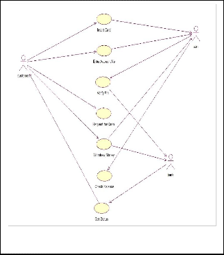
Use case diagram of ATM
UML diagrams are used to model the user requirements. The use case diagram [2] consists of use cases and actors involved in the system. A use case illustrates a sequence of actions that provide measurable value to an actor [2]. An actor represents a person, organization, or external system that plays different role in one or more interactions with the system [8]. The use case diagram of ATM is shown in Fig 2.
Class Diagram of ATM
The class diagram is the basic building block of UML. It de- scribes the structural view of the system by representing the classes, its attributes, its methods and the association among the classes.
In this paper ATM, Bank, Customer are taken as clas- ses. There are various attributes and methods correspond to each class. Here our main emphasis is on ATM class. ATM is having “name of ATM and location of ATM” as attributes and “withdraw(), balance enquiry(), mini statement() etc.” as
IJSER © 2013 http://www.ijser.org
International Journal of Scientific & Engineering Research Volume 4, Issue 1, January-2013 3
ISSN 2229-5518
methods. The class diagram of ATM is shown in Fig 3. 3.2 APPLYING OCL CONSTRAINTS to UML CLASS
DIAGRAM
OCL [5] is a formal language used to represent constraints which is easy to read and write. It is used to describe precon- ditions and post-conditions on operations and methods. Fig- ure 4 shows the Class Diagram associated with UML class diagram.
Context and Self:
OCL expressions are written in the context of an instance of a specific type.
e.g. context Customer
Reserved word self is used to refer to the contextual instance
[16]. If the context is Customer, self refers to an instance of
Customer.
Invariants: Invariants determine a constraint that must be true for all instances of a type.
Pre-condition: Constraint assumed to be true before the oper- ation is executed [16].
Post-condition: Constraint satisfied after the operation is exe- cuted [16].
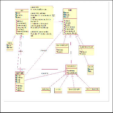
Fig. 2 Use Case Diagram of ATM

Fig. 4 Class Diagram associated with OCL
Constraints considered in ATM in this paper: Preconditions and post-conditions associated with operation withdraw of ATM class is as follows:
Fig. 3 Class Diagram of ATM
context ATM::withdraw(): String
Precondition:
1. PIN number should be valid.
2. Balance should be greater than 500.
3. Amount to be withdrawn should be greater than 100.
Post-condition:
Result - Thank You message and printed receipt, after success-
IJSER © 2013 http://www.ijser.org
International Journal of Scientific & Engineering Research Volume 4, Issue 1, January-2013 4
ISSN 2229-5518
ful transaction.
Result represents the result of the operation, if any. Type of
Result is the result type of the operation [16] (String in the ex-
ample).
4 CPN MODEL
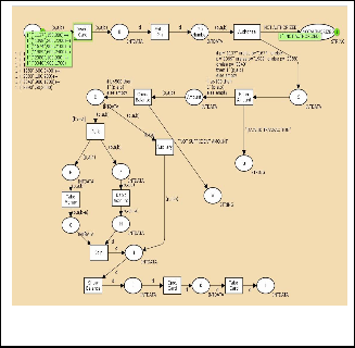
In this paper, we propose a UML-OCL-CPN model that pro- vides an executable and unambiguous UML model. UML models provide a precise and detailed design of the system. Coloured Petri Net is applied on UML-OCL model to make the model executable as well as to show the dynamic nature of the model. In this paper, UML class diagram is adopted as our primary notation for modelling the behaviour and then CPN tool is used to verify and simulate the results. The CPN model of ATM is shown in Fig 5.
greater than the total balance in the account then the ATM will display “NOT SUFFICIENT AMOUNT”. This process is shown in Fig. 7.
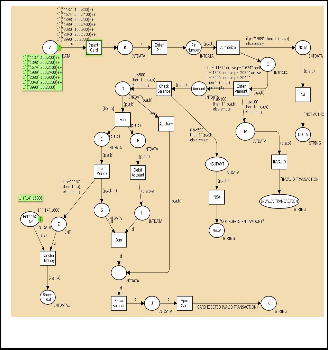
Fig.6. Validating OCL first constraint
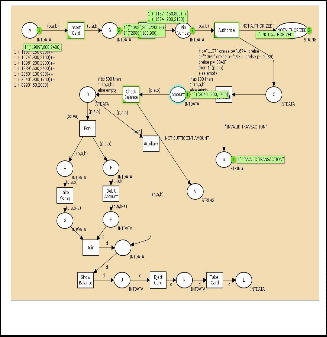
Fig.5. CPN model of ATM
Fig. 5 shows the main page of validation process. In the CPN model, PIN number, amount to be withdrawn are taken as input. Whenever we go to ATM firstly we insert the card, if the card is of another bank then the consortium will check the card whether it is of authorized bank or not. After checking the card, it will check the PIN number which is considered as first OCL constraint. If the user is not authorized or its PIN number is not valid then it gives a message “NOT AUTHOR- IZED” and again asks for PIN number, this will continue upto three times. Within three times, if the user will not be able to give valid PIN number then transaction will be failed and the CPN model will show “INVALID TRANSACTION”. This process is shown in Fig. 6.
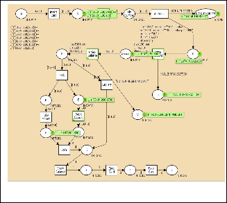
If the user gives correct PIN then the user enters the amount to be withdrawn, this amount should be less than the total amount available in the account. This is considered as second OCL constraint. If the amount to be withdrawn is
Fig.7. Validating OCL second constraint
If second constraint is true, then it checks the third constraint whether the total amount left in the account is greater than minimum permissible amount i.e., 500 or not. If is greater than
500 then it executes completely and gives a printed receipt otherwise it will display an “INVALID TRANSACTION” message. This process is shown in Fig. 8.
IJSER © 2013 http://www.ijser.org
International Journal of Scientific & Engineering Research Volume 4, Issue 1, January-2013 5
ISSN 2229-5518
CPN Tools state space report for:
/cygdrive/C/Users/aaka/Desktop/atm.cpn
Report generated: Fri Mar 23 16:44:19 2012
Statistics
-------------------------------------------------------------- State Space
Nodes: 14
Arcs: 14
Secs: 0
Status: Full
Scc Graph
Nodes: 14
Arcs: 14
Secs: 0
Fig.8. Validating OCL third constraint
4.1 STATE SPACE DIAGRAM
State Space Diagram is generated by using CPN tool. CPN Tools combine advanced interaction techniques into a con- sistent interface for editing, simulating, and analysing CPN [11,12]. CPN Tools contains facilities for generating and ana- lysing full and partial state spaces for CP-nets. The state space diagram of ATM generated through CPN tool is shown in Fig.
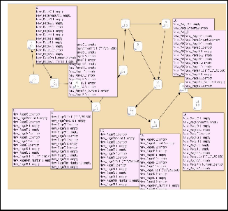
9.
Fig.9. State Space Diagram of ATM
4.2 STATE SPACE REPORT
The state space report is generated by using CPN tool [14]. It contains information about standard behavioural properties for CPNs. These behavioural properties give statistical infor- mation, bounded-ness properties, home and liveliness and fairness properties for transition.
Boundedness Properties
-------------------------------------------------------------- Best Integer Bounds
Upper Lower atm'A 1 1 0 atm'Amount 1 1 0 atm'B 1 1 0 atm'C 1 1 0 atm'D 1 1 0 atm'E 1 1 0 atm'F 1 1 0 atm'G 1 1 0 atm'H 1 1 0 atm'I 1 1 0
atm'J 1 1 0 atm'K 1 1 0 atm'L 1 1 0
atm'PIN_Number 1 1 0
Best Upper Multi-set Bounds atm'A 1 1`("11",150,800) atm'Amount 1 1`("11",150,800) atm'B 1 1`("11",150,800) atm'C 1 1`("11",150,800) atm'D 1 1`("11",150,800) atm'E 1 1`("11",150,800) atm'F 1 1`("11",150,800) atm'G 1 1`("11",150,650) atm'H 1 1`("11",150,650) atm'I 1 1`("11",150,650)
atm'J 1 1`("11",150,650) atm'K 1 1`("11",150,650) atm'L 1 1`("11",150,650)
atm'PIN_Number 1 1`("11",150,800)
Best Lower Multi-set Bounds atm'A 1 empty atm'Amount 1 empty atm'B 1 empty
atm'C 1 empty
atm'D 1 empty
IJSER © 2013 http://www.ijser.org
International Journal of Scientific & Engineering Research Volume 4, Issue 1, January-2013 6
ISSN 2229-5518
atm'E 1 empty atm'F 1 empty atm'G 1 empty atm'H 1 empty atm'I 1 empty atm'J 1 empty atm'K 1 empty atm'L 1 empty
atm'PIN_Number 1 empty
Home Properties
-------------------------------------------------------------- Home Markings
[14]
Liveness Properties
-------------------------------------------------------------- Dead Markings
[14]
Dead Transition Instances atm'Auxiliary 1
Live Transition Instances
None
Fairness Properties
-------------------------------------------------------------- No infinite occurrence sequences.
5 CONCLUSIONS
This paper provides a transformation approach of UML-OCL- CPN to develop a UML model which is highly precise and free from ambiguity. In order to achieve unambiguous model of the system, OCL has been used. These OCL constraints specify the invariant, precondition and post-condition on the attrib- utes and methods of the classes. While applying OCL con- straints, UML associated with OCL model is developed which shows only static structure of the system. To make it executa- ble, Coloured Petri Net is used which shows the dynamic be- havior of the system. Hence, this approach provides an exe- cutable UML model which is highly precise and unambigu- ous.
[4] L. C. Briand, Y. Labiche, H. D. Yan, M. Di Penta, “A Controlled Ex- periment on the Impact of the Object Constraint Language in UML- based Maintainence,” In Proc. Of the 20th IEEE Internatiional Conference on Software Maintainence (ICSM’04), 2004.
[5] L. C. Briand, Y. Labiche and H. Sun, “Investigating the Use of Analy- sis Contracts to Improve the Testability of Object-Oriented Code,” Software Practice and Experience, vol. 33, no. 7, pp. 637-672, 2003.
[6] S. Cook, A. Kleppe, R. Mitchell, B. Rumpe, J. Warmer and A. Wills, “Object Modelling with the OCL, The Rationale behind the Object Constraint Language,” The Amsterdam Manifesto on OCL, in T. Clark and J. Warmer Eds., Springer Verlag, pp. 115-149, 2002.
[7] A. Kleppe, J. Warmer and W. Bast, “MDA Explained- The Model
Driven Architecture: Practice and Promise,” Addison Wesley, 2003.
[8] Thouraya Bouabana- Tebibel, ”Roles at the Basis of UML Valida- tion,” Journal of Computing and Information Technology- CIT 15, pp.
171-183, 2007, doi:10.2498/cit.1000882.
[9] Tadao Murata, “Petri Nets: Properties, Analysis and Applications,”
Proc. Of the IEEE, vol. 77, no. 4, April 1989.
[10] Kurt Jensen, “An Introduction to the Practical Use of Coloured Petri
Nets,” Springer-Verlag, 1996.
[11] Jensen, Kurt, “Coloured Petri Nets: Basic Concepts, Analysis Methods and Practical Use,” vol. 1, Basic Concepts. Monographs in Theoretical Computer Science, Berlin, Germany: Springer- Verlag, 1997.
[12] Kristensen, L. M., Christensen, S., Jensen, K., “The practitioners guide to Colored Petri Nets,” International Journal on Software Tools for Technology Transfer, 1998.
[13] Mark Richers and Martin Gogolla, “On formalizing the UML Object
Constraint Language OCL,” In Proc. Of 17th Int. Conf. Conceptual Mod- elling (ER’98), Springer, Berlin, LNCS vol. 15, pp. 449-464, 1998.
[14] Design/CPN. Online: http://www.daimi.au.dk/designCPN/.
[15] OMG. UML 2.0 OCL Final Adopted Specification. OMG Document
ptc/03-10-1, October 2003, Online: http://www.omg.org/cgi-
bin/doc?ptc/2003-10-14.
[16] Jos Warmer and Anneke Kleppe, “The Object Constraint Language:
Precise Modelling with UML,” Addison Wesley, 1999.
[17] Vijay Gehlot and Anush Hayrapetyan, “Systems modeling and anal-
ysis using Coloured Petri Nets: a tutorial introduction and practical applications,” ACM-SE 45: In Proc. Of the 45th annual southeast re- gional conference, 2007.
[18] G. Booch, J. Rambaugh, and I. Jacobson, “The Unified Modelling
Language User Guide,” Addison Wesley, 1999.
The future scope of this paper is to validate OCL con- straints on overall Banking Information System using CPN modelling concept.
.
REFERENCES
[1] Michael R. Blaha, James R. Rambaugh, “Object-Oriented Modelling and Design with UMLTM,” Pearson Education, Inc and Dorling Kindersley Publishing, Inc, 2005.
[2] Rambaugh J., G. Booch, and I. Jacobson, “The Unified Modelling
Language,” Reference Manual, Reading MA: Addison Wesley, 1999. [3] Ali Hamie, John Howse and Stuart Kent, “Interpreting the object
Constraint Language,” Inc. Proc. Of 1998 Asia Pacific Software Engi-
neering Conference, pp.288-295, 1998.
IJSER © 2013 http://www.ijser.org