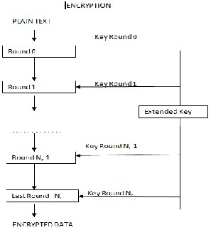
Figure 1:Secure Encryption using key
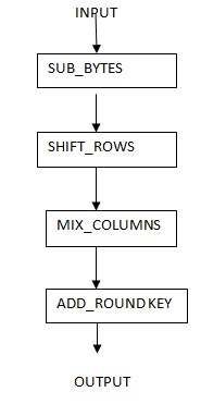
Figure 2:Variouse steps in the encryption.
International Journal of Scientific & Engineering Research, Volume 4, Issue 4, April-2013 195
ISSN 2229-5518
A Lossless Watermarking Using Histogram Shifting
Algorithm
Asst. Prof. Gauri Mahabaleshwar Samant, M.Tech,
Department of Computer Engineering,
Goa College of Engineering, Farmagudi, Ponda , Goa, India.
Email- gaurimgsamant@rocketmail.com
Asst.Prof.Rhicha Jambhale, M.E,
Dept. Information Technology,
Padre Conceicao College of Engineering, Verna, Goa. rhicha.jambhale@gmail.com
Abstract— The watermarking of digital images, audio, video and multimedia products are used for copyright ownership and verifying originality of contents. Domain wavelet transform used in the visible watermark does not provide security for watermark. Vis ible watermark methods do not provide safety for both watermark and carrier image. To overcome that , lossless watermarking using histogram shifting algorithm is proposed. The carrier image carries watermark . The carrier image can be stored lossless af ter the extraction of watermark from it. Histogram Shifting algorithm is used to embed watermark logo in the carrier image . By using the Rijndael algorithm , the error is spread to the entire image. So the illegal user can not access the watermark image from ca rrier image. This algorithm can guarantee the quality of the image and safety of watermark. Add Roundkey and shift rows transformation provides more security for encryption than other methods.
Keywords-lossless watermarking; visible watermark; rijndael
I. INTRODUCTION
Digital watermarking is one of the ways to prove the ownership and the authenticity of the media.There are many digital watermarking classification methods. According to the external appearance, the digital watermarking can be divided into visible digital watermarking and invisible digital watermarking. Invisible digital watermark it embeds directly into digital media (including multimedia, documents, software, etc.) without prejudice of the original carrier value, and their watermark logo is not visible, not easy to be perceived system (such as visual or auditory system) perceived or noted. For images, this watermark is an invisible watermark logo. The watermark embedded in the visible digital watermark image has clear visibility, and compared to the simple image overlay, the embedded watermark image can recover lossless, hiding the integrate data which is needed to eliminate the watermark, by some calculation operation to extract hidden information, removing the watermark and restore the source data. For images, this watermark is a visible sign of performance[1,3]. For visible watermarking, the watermark should be perceptually visible and robustness.
Invisible Watermarking | Visible Watermarking | |
Watermark perceptibility | Imperceptible distortion | Visibly meaningful pattern |
Robustness | Intentional attacks and common signal processing | User intervention based watermark removal |
protection | Passive | Active |
extraction | Explicit extraction module | Direct Viewing |
Current research status | Any papers | Only few papers |
IJSER © 2013 http://www.ijser.org
International Journal of Scientific & Engineering Research, Volume 4, Issue 4, April-2013 196
ISSN 2229-5518
This highlights the necessary for lossless reversible watermarking, which can recover the original host signal perfectly after the watermark extraction. Most of the existing lossless watermarking algorithms are focus on invisible watermarking , however “lossless” property is more important in visible watermarking than that in invisible watermarking as generally visible watermarking causes great distortion than that of invisible watermarking.
The current study about the visible watermarking is very less, the proposed scheme of visible watermarking is usually destructive, and the loss visible watermark technology would undermine the image quality, limits its applications, the original image of this method is non-destructive image reproduction, overcoming the shortcomings of the destruction in image quality. Some researchers used wavelet transform for lossless and visible watermarking, this algorithm uses wavelet transform, which computes more complextiy, and the hidden data is limited. This text uses the method of histogram shifting to mask the sub-image information, shelter more information, and attain the purpose to limit unauthorized use.
II. PROPOSED ALGORITHM
A. Histogram Shifting Algorithm
Histogram shifting is a lossless data hiding method, its advantage is that the data embedded is large,visibility is good,the peak signal to noise ratio is high.
Suppose the original image is I, for example in the color image, this paper selects 24-bit true color image as a original image, so we can get Ir , Ig , Ig the three color layers of the image. Concealed image first encrypt as RH arithmetic operator. So as to be hidden as encrypting information w, and then divide w into three sections w =wR + wG +wB , each
’ ’
hidden in Ir, Ig , Ib , the three color layer image. The three-tier image after hiding image information recorded as Ir’ , I g ,Ib . For
example in the Ir layer, the process of hiding wr follows:
B. Watermark Embedding Algorithm
Step 1:Generate the original image histogram denoted by H(I).
Step2:In the H(I) search for h(b)=min{h(k),kϵ[0,255]},simply we might suppose h(b)=0.Then search for h(a)>=L/3,aϵ[0,255].L is
the hidden message wr’s length.set a,b as a key record.
Step3:In the open interval (a,b) of gray values in Ir with in the pixel gray increased by 1 (if b<1 reduces to 1).
Step4: Progressive scan original image, embedded L/3 bit information. For the carrier image Ir pixel whosegrayvalue is a, contrast
to the to be embedded hidden information, if current embedded information bit is 1, it serves to increase
the pixel gray value 1 (if b< a , then reduction of 1); if the current embedded information bit is 0, then pixel gray value keep this constant. The other pixels in the image do not need to change.
Step5:step2 to step4 cycle 3times.
At this point, Wr been embedded into the image Ir ,get the watermarked image Ir’. Embedded interval endpoints a, b
as the key saved in part by a watermark extraction side. Hiding algorithm process
C. Rijndael Algorithm
Rijndael,the advanced encryption standard is a symmetric block cipher.It uses the same key between the sender and receiver to encrypt and decrypt the message.Speed and cost make symmetric algorithms as the algorithm of choice for encrypting large amounts of data. It is an iterated block cipher with variable block length and variable key length. More the key length more the security. The block length and the key length can be independently specified to 128, 192 or 256 bits with the constraint that the input and the output have the same length. Internally Rijndael operations are performed on a two dimensional array of bytes called the state. All the intermediate cipher and inverse cipher results are stored in the state. This array has four rows. The number of columns represents the data block length to be encrypted divided by
32 and is denoted by Nb. At the start of the cipher and inverse cipher operations, the input block is copied into the state array; the cipher or inverse cipher operations are then conducted on this state array. many mathematical operations within Rijndael ciphertext algorithm.
IJSER © 2013 http://www.ijser.org
International Journal of Scientific & Engineering Research, Volume 4, Issue 4, April-2013 197
ISSN 2229-5518
Figure 1:Secure Encryption using key
Figure 2:Variouse steps in the encryption.
IJSER © 2013 http://www.ijser.org
International Journal of Scientific & Engineering Research, Volume 4, Issue 4, April-2013 198
ISSN 2229-5518
The cipher key is similarly considered as a rectangular array with four rows. The number of columns is equal to the key length divided by 32, and denoted by Nk. The number of rounds is denoted by Nr, and depends on the values of Nb and Nk . For example when Nk=4, Nb=6, then Nr=12.
Number of rounds Nr as a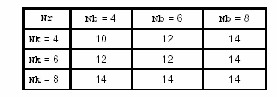
D. Shift Row Transformation
In ShiftRow, the rows of the State are cyclically shifted over different offsets. Row 0 is not shifted, Row 1 is shifted over C1 bytes, row 2 over C2 bytes and row 3 over C3 bytes. The shift offsets C1, C2 and C3 depend on the block length Nb. The different values are specified in Table (2). The operation of shifting the rows of the State over the specified offsets is denoted by:ShiftRow (State).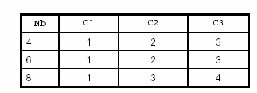
inverse of ShiftRow is a cyclic shift of the 3 bottom rows over Nb-C1, Nb-C2 and Nb-C3 bytes respectively so that the byte at position j in row I moves to position ( j + Nb Ci) mod Nb.
E. Mix Column Transformation
In MixColumn, the columns of the State are considered as polynomials over GF(28 ) and multiplied modulo x 4 + 1 with a fixed polynomial c( x ), given by:
This polynomial is co-prime to x 4 + 1 and therefore invertible. This can be written as a matrix multiplication. Let s’(x
![]()
) = a(x ) s(x ), four bytes in a column are replaced by
It is given by:
F. The Round key Addition
In this operation, a Round Key is applied to the State by a simple bitwise EXOR. The Round Key is derived from the Cipher Key by means of the key schedule. The Round Key length is equal to the block len gth Nb. The transformation that consists of Exporting a Round Key to the State is denoted by:AddRoundKey(State,RoundKey).
IJSER © 2013 http://www.ijser.org
International Journal of Scientific & Engineering Research, Volume 4, Issue 4, April-2013 199
ISSN 2229-5518
G. Extraction
It is easy to see through the embedding process that histogram shifting is completely reversible in the case of getting the key, when extracting the watermark we need only omitted the second step and exchange the order of the fourth step and third step.
Step 1: The key ak,bk.
Step 2:Search for the pixel whose gray value is ak,ak+1,if ak ,extracting o,if ak+1,extracting 1,until extracted L/3 bit.
Step 3:In the open interval (ak,bk) of gray values with in the pixel gray value decreased by 1.
Step 4:Reconstruction of the original image I and the Watermark w.
F. LOSSLESS PARAMETERS
We have to calculate PSNR and MSE.PSNR , peak signal noise ratio is used to calculate the quality of the recovered image. It is a better test since it takes the signal strength in to consideration.![]()
where, MSE is the mean square error between the original image and the watermark recovered image. This is used to test whether two pictures are similar or not.
The definition of MSE is given by:![]()
where, xi,j and x'i,j are the pixel values of the original image and the watermark recovered image, respectively. A higher
PSNR value means that the quality of lossless restore image is closer to the original image.
In histogram-shifting method, when two pairs of peak and minimum points are used to embed data, all pixels are plus or minus one grayscale unit at most, resulting the MSE between the original image and the lossless restor e image is close to 1. Therefore, the lower bound of PSNR is given by:
PSNR≥10xlog10 2252 = 48.13 db
III .EXPERIMENTAL RESULTS
To verify the algorithm, we make use of four standard color images in the experiment, the watermarks are visibly embedded to verify whether the lossless representation of the original image![]()


a1 b1 c1 d1
IJSER © 2013 http://www.ijser.org
International Journal of Scientific & Engineering Research, Volume 4, Issue 4, April-2013 200
ISSN 2229-5518
![]()


a2 b2 c2 d2
![]()


a3 b3 c3 d3
![]()


a1 b4 c4 d4
figure: a,b,c,d represents the original image,watermark,watermarked image,lossless restore image
IV. CONCLUSION
In this paper, we have introduced a lossless recovery with visible digital watermarking technology. Through histogram shifting we achieve hiding and recovering the information lossless, resolving the destruction of original images in visible digital watermark, as well as the small amount of information hidden problems. for more security, we are using Rijndael encryption algorithm to encrypt the data of sub image, spreading a disturbance to the whole image, so as to achieve the purpose of protecting the image data with high security. The visible digital watermark by concealing parts of the image restricts the use of illegal users to protect the image. It can completely replace the use of a sign ofthe overlaying watermark image with a wide range application.
REFERENCES
[1] Voyatzis G, Ipitas. The use of watermarks in protection of digital multimedia products. Proceeding of IEEE, 1999, 87(7): 1197-1207 .
[2] Luo Y. , Cheng L.Z. , Xu Z.H. et al . A visible watermark based on integer wavelet transform with parameters. Journal of Software ,2004 , 15(2) : 238�249 (in Chinese)
[3] Cui D.L,Ling B.A visible watermarking algorithm based on wavelet domain with lossless recovery.Journal of Tibet University.2008 ,23(1):111-114.
[4] Servetto S. D. Podilchuk C. I., Ramchandran K. Capacity issues in digital image watermarking, IEEE Intl Conf on Ima ge Processing,Chicago, Illinois, USA,
1998, 445-449.
[5] Zhang B., Jalal M. F. and Jean L. Wavelets, Ridgelets, and Curvelets for Noise Removal.IEEE trans. On Image Processing. 17(7) 2008, 1093-1108. [6] Cui D.L,Ling B.A visible watermarking algorithm based on wa velet domain with lossless recovery.Journal of Tibet University.2008,23(1):111 -114
[7] “R. C. Merkle, One-way hash functions and DES. In AdvancesCryptology, CRYPTO’89, Lecture Notes in Computer Science,1989,435: 428 -466.
IJSER © 2013 http://www.ijser.org