International Journal of Scientific & Engineering Research, Volume 4, Issue 6, June-2013 69
ISSN 2229-5518
A GUI (Graphical User Interface) framework For distribution automation through CAN (Control Area Network) Protocol
Mr. Nilesh Yadav, Prof. Neeraj kumar
Shri Satya Sai Institute of Science and Technolog SH-18 Bhopal Indore Road
Opp. Oil Fed Plant Sehore (M.P)
{nileshyadavy@gmail.com}
—————————— ——————————
in a distribution automation (DA) system, the various quanti-
ties (e.g., voltage, current, switch status, temperature, and oil
level) are recorded in the field at the distribution transformers
and feeders, using a data acquisition device called Remote
Terminal Units (RTU). These system quantities are transmitted
on-line to the base station (33kV substation) through a variety
of communication media. The media could be either wireless
(e.g., radio, and pager) or wired (e.g., Dial-up telephone, RS-
485 multi-drop, and Ethernet). The measured field data are
processed at the base station for display of any operator se-
lected system quantity through Graphic User Interface (GUI).
In the event of a system quantity crossing a pre-defined
threshold, an alarm is automatically generated for operator
intervention. Any control action (for opening or closing of the
switch or circuit breaker) is initiated by the operator and
transmitted from the 33kV base station through the communi-
cation channel to the remote terminal unit associated with the
corresponding switch or circuit breaker. The desired switching
action then takes place and the action is acknowledged back to
operator for information.With the advancement in technology,
several new methods [1] are evolving in the automation sector.
Some most popular of them are LAN(Local Area Networking)
[2], PLC[3] (Power line communication) , ZigBee[4][5] , CAN (Con-
trol Area Network) etc.
Our work focuses on developing a graphical user interface
(GUI) in Matlab , which will simulate and monitor several different physical parameters and also the GUI will take ap- propriate action with or without human intervention. For the rest of the paper we will refer GUI as console master computer (CMC) , since it is acting as a master CAN node as well as sev- eral slave nodes.
Controller Area Network or so-called CAN is a serial bus that utilizes broadcast method to transmit messages across all CAN nodes[6]. It uses a serial control protocol which provides reliable, efficient and economic link between devices to sup- port the distributed real time applications by using a bitwise deterministic collision-resolution mechanism. It was originally developed in the 1980s by Robert Boush as an alternative data communications for interconnecting the control components in automotive vehicles. Prior to CAN technology, all manufac- turers used to connect devices within vehicles using point to point wiring systems. Wiring started to become more complex, bulky, heavy and expensive as more electronics and control- lers are deployed in a vehicle. This problem can be seen in Figure 1(a), where the abundance of wiring is required
which makes the whole circuit even more complicated. CAN
system can solve this problem by utilizing a twisted pair cable
IJSER © 2013 http://www.ijser.org
International Journal of Scientific & Engineering Research, Volume 4, Issue 6, June-2013 70
ISSN 2229-5518
to communicate with each other as shown in Figure
1(b).Initially, it was designed to allow the microcontrollers and
devices to communicate with each other within a vehicle
without a host computer. It has been fast gaining wide appre-
ciation with further applied in various automation distribution
including military, aviation, electronics, factories and many
others due to its high immunity towards electrical interfer-
ence, and the ability to self diagnose and repair the data er-
rors. Additionally, the low cost, performance and upgradeabil-
ity to provide tremendous flexibility in the system design add
to its many advantage. [7]
Fig 1.(a): Traditional Wiring
Fig 1.(b): CAN Wiring
3. CAN Protocol
The CAN system uses carrier sense multiple access with colli- sion detection (CSMA/CD) and arbitration on message priority as its communication protocol. This communication protocol allows every node in CAN to monitor the network bus in ad- vance before attempting to transmit a message. When no activ- ity occurs in the network, each node has the same opportunity to transmit a message[8]. Additionally, this communication pro- tocol allows collision to be solved by using bit-wise arbitra- tion. It is based on a pre-programmed priority of each message in the identifier field of a message. This configuration allows the messages to remain intact after the arbitration is completed even if collisions are detected. In order for the arbitration pro- cess to be successful, the logic states need to be defined as dominant or recessive. An example of CAN arbitration can be seen in Figure 2 when three nodes are assumed to be transmit- ting simultaneously.
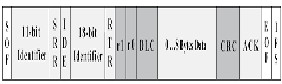
When three nodes start transmitting their start of frame(SOF) bits simultaneously, the Nodes 1 and 2 stop transmitting as soon as they transmit bit ‘1’ (recessive level) while Node 3 is transmitting bit ‘0’ (dominant level). At this instance, Node 3 will continue its transmission when the identifier of bit ‘0’ has been transmitted while Nodes 1 and 2 are entering into the receiver mode which indicated in grey color. The CAN protocol is defined with the ISO standard of
11-bit identifier that provides for the signaling rates from 125
kbps to 1 Mbps. This standard is later improved to allow for
larger number of bit with the "extended" version of 29-
bit identifier. The 11-bit identifier standard provides 211 or
2048 different message identifiers while the extended 29-bit
identifier standard provides 229 or 537 million identifiers[9]. The
data format of both standards can be seen in Figure 3.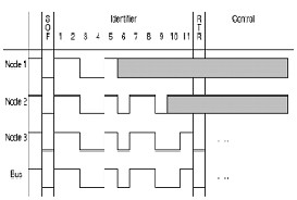
Fig. 2 CAN Arbitration
IJSER © 2013 http://www.ijser.org
International Journal of Scientific & Engineering Research, Volume 4, Issue 6, June-2013 71
ISSN 2229-5518
Fig 3(a) Standard CAN Format
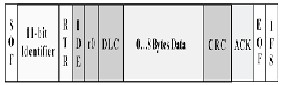
Fig 3(a) Standard CAN Format
Console master computer (CMC) is a GUI built on Matlab software.CMC performs many functions which includes :-
a) Fixing the set point
b) Visualizing data for future use. c) Start/Stop Communication
d) Enable Data Logger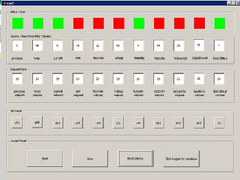
The CMC is based on Vehicular Network Toolbox (VNT) pro- vided by Matlab.Figure (4) shows the complete GUI. The GUI consists of a status panel which gives the status of current physical node.
Since in an actual setup the various physical nodes will be communication through there own controllers , we have in our simulation , connected them through a loopback mechanism. Two CAN channels are created which are connected in loopback mechanism through VNT , the two channels are sending data through the matlab environment. The current values for various nodes are generated through a random number generator. The random values are then transmitted through the specifies CAN channels and received by another CAN channel. The CMC then analyses the data and compares it with the set point fixed by the user. If the random value exceeds the set point then the CMC sends OFF command to the physical node through CAN bus.
Fig. 4 Complete GUI Layout
Throughout the process the data of the physical node is stored in the program for plotting and analysis purpose the user at any time can view the plot for the data.
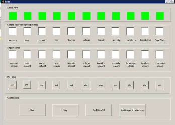
Also for visual inspection , the status of phys- ical node changes from green to red indicating that a stop command is given to that particular node. Figure (5) shows the GUI for a particular time instant and the status of the nodes are also visible.
Fig. 5 Snapshot of Sample GUI for a particular time
The plot utility provides a great facility for the supervisor in
IJSER © 2013 http://www.ijser.org
International Journal of Scientific & Engineering Research, Volume 4, Issue 6, June-2013 72
ISSN 2229-5518
an actual distribution setup. With the help of plot button, the supervisor can visually inspect the values coming from the physical nodes and also the set point allocated for that particu- lar node . This allows the supervisor to check for any discrep- ancy that may have crept in at an earlier time. Figure 6 shows the graph displayed by the plot button for the physical node labeled RPM, the graph clearly indicates all the parameters that are required in an distribution setup.
The CMC also allows the user to start logger for the whole communication session. With the help of data log- ger, the VNT will store all the data appearing on the CAN bus into a CAN data bus file. This file can be used forfurther supervisory analyses.
Table 1 shows the comparisons between CAN, PLC and LAN. The price for developing a CAN node is about RM 60 which is lower compared to the PLC and LAN. In terms of transmis- sion medium and rate, CAN uses a twisted copper pair that is capable to make transmission with a rate of 1 Mbps. Although PLC and LAN provide higher transmission rate compared to CAN, they have not been selected because low transmission rate is sufficient to control low consuming data without signif- icant time delay. Moreover, CAN have added advantages such that it is immune to electrical interference compared to PLC which is susceptible to electrical interference. Also, LAN is vulnerable to interference from other transmission source. Nevertheless, the coverage area for CAN[10] is not restricted compared to LAN and PLC. A home appliance can be controlled as long as it is attached to the CAN node which is connected to the CAN bus.
Table 1 Comparison between CAN , LAN and PLC
In this paper, the distribution automation system using CAN as the main communication protocol to control multiple phys- ical nodes has been presented. Based on the simulation results, the proposed system has the capability of controlling physical nodes in industry accurately and effectively with minimal time delay. Moreover, the proposed system has the advantages of being simple in its design which contributed to the overall low cost. Also, by using CAN, the network system is free from electrical interferences as it is immune to it.
1. M. G. Golzar, and H. Tajozzakerin, “A New Intelligent Remote Control System for Home Automation and Reduce Energy Consumption,” Fourth Asia International Conference on Mathematical/Analytical Modelling and Com- puter Simulation (AMS 2010), pp. 174 - 180, 26 – 28 May 2010.
2. D. D. Clark, K. T. Pogran, and D. P. Reed, “An Introduction to Local
Area Networks,” Proceedings of the IEEE, vol. 66, no. 11, pp. 1497 - 1517,
1978.
3. K. S. Surendran, and H. Leung, “An Analog Spread-Spectrum Interface for Power-Line Data Communication in Home Networking,” IEEE Trans- actions on Power Delivery, vol. 20, no. 1, pp. 80 - 89, Jan. 2005.
4. S. Dagtas, G. Pekhteryev, and Z. Sahinoglu, “Multi-Stage Real Time Health Monitoring via ZigBee in Smart Homes,” 21st International Conference on Advanced Information Networking and Applications Workshops (AINAW 2007), vol. 2, pp. 782 - 786, 21 - 23 May 2007.
5. X. H. Li, K. L. Fang, J. G Gu, and L. Zhang, “An Improved ZigBee Rout- ing Strategy for Monitoring System (ICINIS 2008),” First International Con- ference on Intelligent Networks and Intelligent
Systems, pp. 255 - 258, 1 - 3 Nov. 2008.
6. R. B. GmbH, “CAN Specification,” version 2.0, 1991.
7. K. Pazul, “Controller Area Network (CAN) Basics,” Microchip
Technology Inc, 1999.
S. Corrigan, "Introduction to the Controller Area Network (CAN)," Texas strument, Application Report, July 2008.
M. Farsi, K. Ratcliff, and M. Barbosa, “An Overview of Controller Area
etwork”, Computing & Control Engineering Journal, vol.10, no. 3, pp. 113 -
0, August 1999.
. J. Liu, G. Y. Hu, and X. H. Wen, “DSP and CAN Bus Based Induction otor Control in Electrical Vehicle Application,” Sixth International Confer- e on Electrical
achines and Systems .
IJSER © 2013 http://www.ijser.org