Inte rnatio nal Jo urnal o f Sc ie ntific & Eng inee ring Re se arc h, Volume 3, Issue 3 , Marc h-2012 1
ISS N 2229-5518
A Fuzzy Logic Solution for Feed Drive Control
Ferit Idrizi, Jorgaq Kacani,
Abs tract— Because of high speed conditions of w ork and nonlinearities during machining the f eed drive mechanism of vertical milling machine it becomes a very diff icult model to be designed and controlled. In th is paper w e try to f ind a f ast solution to overcome these problems and it is an attempt of f inding alternative easiest w ays of successf ul f uzzy logic control imple mentation. We propose an approach that off ers some stability characteristics and very good computational perf ormances eff iciency. The controller gives f ast loo p response stability, reducing the steady state error, increasing the rising time and decreasing the settling time.
Inde x Terms— Fuzzy logic, f eed drive, CNC, me mbership function, control, intelligent control, PID
—————————— ——————————
1 INTRODUCTION
sually today’s CNC machine tools have high speed spindle motors and high -power servomotors with high-lead ball-screws. [1] During high speed and high
accelerations work conditions, the main issue is vibration, respectively machining accuracy losses in term of path tracking errors, positioning errors, wavy and spoiled surfaces of the parts, etc Generally these feed drives are designed using a rotary servomotor and a ballsc rew. The most common motors used in the feed drive are dc motors since they allow a wide range of operating speed with a sufficiently large torque delivery required by machine tools. This torque produced by the motor is spent in acceleration of inertia reflected in the motor shaft, overcoming the friction in the motor contact surfaces, friction in the mechanical part of feed drive as guideways, bearings and resisting against feed cutting forces.[2] But when a high speed command is given, that causes problems with controlling the relative movement between work piece and the tool because of vibration and inertia in the mechanical system. To overcome all these nonlinearities and difficulties during the system control, over the years have been used various PID based controllers, in order to improve the dynamic characteristic of the feed drive control loop. By fuzzy logic we can model imprecise concepts and by different weights of defining conjunction and disjunction and fuzzy set negation, we can manage different nature of nonlinearity behaviors of the system.
Optimization is achieved by setting the dynamic range of the fuzzy sets according to tuning process results on MatLab. Considerable improvements are shown on the output response of the system by reducing overshoot, rising and settling time.
Simulated results made by using MATLAB/
SIMULING shows the relevant effectiveness of its applications by errors comparison between conventional and applied controller.
———— ——— ——— ——— ———
Ferit Idrizi,Mr.sc. Faculty of Mechanical Engineering, Prishtina
University, Kosovo-PHD student at Polytechnic University-Tirana.,
2 THE M ODEL
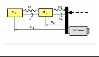
The feed drive mechanisms of a three-axis vertical milling machine consist of a DC motor and a lead-screw with recirculating balls. The DC servomotor which is directly connected to lead-screw shaft drives the table and work piece. [3] The motor, for a short period of time, have to deliver a high dynamic torque to accelerate the lead-screw assembly and the table with work-piece, which means a high peak torque delivery at the start, until the drive reaches the desired steady state speed, and a sufficiently high continuous torque delivery range to overcome the friction in the sideways and feed drive bearings and also the cutting force. [3]
Fig.1. Tw o-mass system of f eed drive (xl-load position and xd-detector position) [4]
This is a typical mechatronic system and can be divided into three parts: mechanical structure, drive mechanism and control system. For this servomechanism, the transfer functions of the individual system components are usually known or have to be calculated. The electrical part, it is presented by a transfer function (1) according to [3] and, gives a actuator force to the second part which is the model of mechanical system and which is simplified to a two-mass system with a spring an d a damper element as shown in fig.1. [4]
+37744350337,E-mail: f.idrizi@seeu.edu.mk
Jorgaq Kacani Acad. Prof. Dr-Tirana Polytechnic University, tel.
+355682060963, E-mail:jorgaqkacani@yahoo.com
IJSER © 2012
http :// www.ijser.org
Inte rnatio nal Jo urnal o f Sc ie ntific & Eng inee ring Re se arc h, Volume 3, Issue 3 , Marc h-2012 1
ISS N 2229-5518
Fm (t) num / den; num 2, den s 2 12s 24
(1)
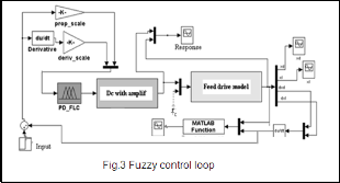
fuzzy block for fuzzy logic inference system. After derivation and Fuzzy block it is made amplifications of the signal, according to [4] (fig.3).
For simulations purposes, the dynamic characteristics
of the mechanical components of feed drive of are
calculated based on the laws of physics and are modeled
using higher mathematics. The MatLab implementation is made by a program of S-function.
3 PID CONTROL
Firstly, the control of the system is simulated by a basic conventional PID controller which contains the proportional gain with scaling factor Kp, the Integral gain scaling factor Ki and the Derivative scaling factor Kd. The proportional, the integral and the derivative terms are summed to calculate the output of the PID controller.
1.2
1
X: 1.56
Y: 0.9969
0.8
0.6
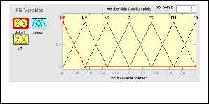
We applied a MISO system with two input signals: deltaT for “error” as a difference between the desired speed and the actual speed, and, dT for the “rate of change” (error derivative). The single output is a combination of these two signals and determines the speed of the actuator. Within the range of [-1, 1] are sets seven symmetric triangular sets for all three variables (fig.4).
0.4
0.2
0
0 0.5 1 1.5 2 2.5 3 3.5 4
Time (Seconds)
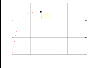
Fig.2. Response from PID control
Looking for the optimum values for the desired control response we have to tune the control closed loop by adjusting of its control parameters (gain/proportional band, integral gain/reset, derivative gain/rate). Generally, stability of response is required and the mechanism must not oscillate for any combination of process conditions and set-points. The most effective methods generally involve the development of the model and choose P, I, and D based on the dynamic model parameters. Common performance criteria include the elements of step response of the system such as: overshoot, rise time, settling time and decay ratio. Even it can be relatively inefficient, initially has been used the manual tuning method. A large value of Kp is chosen and the two others Ki and Kd are set to be zero, then gradually Kp is minimized near to set-point in order to give best response. Ki and Kd are increased in order to reduce steady state error by Ki and reduce the overshoot by Kd. Rise time is improved by readjusting of Kp. So, obtained values are: Kp=50, Ki=40 and Kd=9 (fig.2).
4 FUZZY LOGIC CONTROL
The model contains a PD controller in combination with
Fig.4. Fuzzy sets

The result from this simulation show considerable improvement in term of performance criteria (Fig.5).
Fig.5.FL C transient response
Following the error size and its change rate after the
IJSER © 2012
http :// www.ijser.org
Inte rnatio nal Jo urnal o f Sc ie ntific & Eng inee ring Re se arc h, Volume 3, Issue 3 , Marc h-2012 1
ISS N 2229-5518
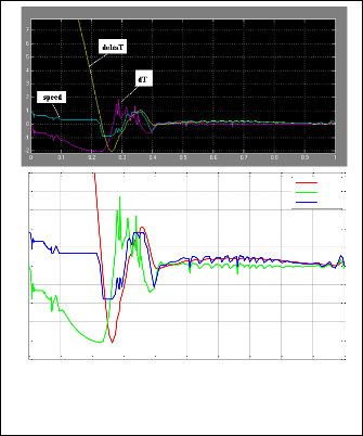
simulation with fuzzy logic controller we can see that if the output goes away from the desired set point, fuzzy logic drive it back toward the set point. (fig.6)
2.5
2
1.5
Gabimet ne hyrje dhe dalje te rr.PD LC
F
deltaT dT speed
1
0.5
0
-0.5
-1
-1.5
-2
-2.5
0 0.1 0.2 0.3 0.4 0.5 0.6 0.7 0.8 0.9 1
Time (Seconds)
Fig.7 Errors after fuzzy block
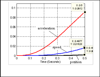
Fig.6 Errors af ter f uzzy block. In order error-change of error-f uzzy logic error
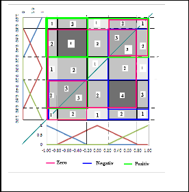
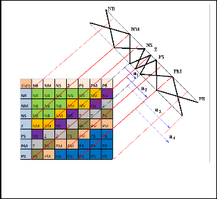
We could only analyze error’s size and changing conditions in the real model to see which rule condition to take for inference. The fig. 9 shows that we have multiple repetitions of some areas which mean in the same time that we increase the degree of uncertainty (numbers 4, 3, etc).
We also see that every change of error causes fast reaction of fuzzy system (fig.7). This mean that we should reduce some inference rules that have the same output, or, to give them other quality grade.
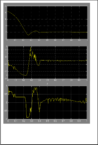
These developments happens between time 0, 2 and 0, 3
at the same time when starts deviation between position,
speed and acceleration of the table (fig.8).
In order to optimize fuzzy logic systems, have been
employed various modifications of membership functions
using genetic algorithms, neural networks, etc. We didn’t use any optimization of those, but we attempt to show that the fuzzy can work very well and for same operating conditions can perform better than PID.
Fig.8. Output of the system
IJSER © 2012
http :// www.ijser.org
Inte rnatio nal Jo urnal o f Sc ie ntific & Eng inee ring Re se arc h, Volume 3, Issue 3 , Marc h-2012 1
ISS N 2229-5518
After this conclusion, we reconstructed the fuzzy system and simulated the loop with fuzzy file PD_FLC_O. The surface view of the inference system it is given in fig. 11.
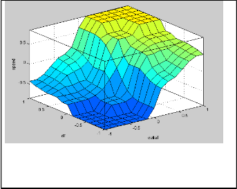
Fig.9. Fuzzy interf erence example
From the practical view, also, it is well conformed that random errors which affect position accuracy that takes place to around 50-70 % of overall errors. Using this area dispersion we could manage to focus the system on the smaller errors by giving them more membership grade than others (Ec.2, fig.10).
Fig.11.The surf ace view
5 R ES ULTS AND COMPARISON
a1 v0
u0
2u0
21u0
2
After simulation process on MatLab, we can see considerable improvements in term of reducing the rise
a2 v1 u1 4u0 2 u0
3
time, settling time, overshoot an steady-state error (Table 1)
. Comparing with PID, the FLC controller with symmetric
a3 v2 u2 8u0 2 u0

an 2 n u0
(2)
triangular and asymmetric membership functions, can reduce rising and settling time, but not the overshoot either. To do that we need to determine we(l2l )the grade for
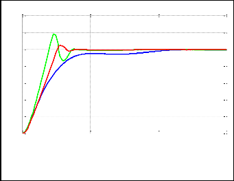
every membership function by using a symmetric triangular sets. This will reduce obviously the both positive and negative overshoots( fig 12).
1.4
Krahasimi_PID_PDFLC_PDFLCO
1.2
1
0.8
0.6
0.4
0.2
Fig.10. New shapes of membership f unctions
0
0 0.5 1 1.
Time (Seconds)
Fig.12. PID-FL C-FL C_O comparison
IJSER © 2012
http :// www.ijser.org
Inte rnatio nal Jo urnal o f Sc ie ntific & Eng inee ring Re se arc h, Volume 3, Issue 3 , Marc h-2012 1
ISS N 2229-5518
TABLE 1. THE PERFORMANCE COMPARISON | |
| Ris e time Overs hot Se ttling Pe ak time | |
PID FLC FLC_O | 0.7667 0.0005 1.877 1.0005 0.1798 0.179 0.804 1.179 0.379 0.046 0.3816 1.046 | |
| |
6 CONCLUSION
Using the fuzzy logical reasoning and approach and by its implementation on control systems we can improve the performance of the control process in a more effective way. We don’t have to use precise values and numbers for the input but by an imprecise inputs data and their interfacing on the feedback control systems, the FLC could generate sufficient system’s reaction for drastically improvement of performance. So, FLC can be a right solution especially when:
-output goes away from the desired set point
-output remains persistently displaced from the desired set point
-output is changing too fast
REFERENCES
[1] Kotaro Nakaoka and Tomonori Sato,” Feedforward controller for continuous path control of CNC Machine Tools”, Advanced Technology R&D Center,Mitsubishi Electric Corporation8-1-1 Tsukaguchi- honmachi,Amagasaki, Hyogo 661-8661, Japan
[2] Atsushi Mastsubara,Yoshiaki Kakino and Yasumi Watanable,”Servo
performanceenhasenment of highspeed feed drives by damping control”
(Conference proceedings) july 2000. Flexible Automatiation Conference,
AnnArbor, Michigan
[3] Jusuf Altintas, “Manufacturing Automation”,book published in 2000.-
Cambridge University Press 2000, pp.160-161
[4] Sheroz Khan, Salami Femi Abdulazeez, Lawal Wahab Adetunji, AHM
Zahirul Alam,Momoh Jimoh E. Salami, Shihab Ahmed Hameed, Aisha HasanAbdalla and Mohd Rafiqul Islam, “Design and Implementation of an Optimal Fuzzy Logic Controller Using Genetic Algorithm”,Jurnal of coputer sciance 4, 2008(Pablished paper)
IJSER © 2012
http :// www.ijser.org