1325
International Journal of Scientific & Engineering Research, Volume 6, Issue 2, February-2015
ISSN 2229-5518
A Comparative Study on Beam Strengthened
with Externally Bonded FRP Material
Tanni Alam Dola and Md. Zakaria Ahmed
Department of Civil Engineering, Bangladesh University of Engineering and Technology, Dhaka-1000, Bangladesh
Abstract-In this research work, parametric study is performed to compare the influences of design parameters on flexural moment capacity of externally bonded FRP (Fiber Reinforced Polymer) strengthened beam. Three specific design guidelines: ACI 440.2R-08, ISIS CANADA and TR-55are considered. In this purpose MS Excel is used to determine the moment capacity for variable parameters specified in the above mentioned three codes. Graphs of capacity against these parameters are plotted to make the comparison well-defined. The three influential parameters that are used in this study are FRP reinforcement, FRP modular ratio, FRP ultimate strength. Most of the parameters under this study influence the flexural moment capacity. The effects of the parameters vary depending on the analysis procedure and the assumption behind of these analyses. Also most of the cases, the effects of these influential parameters increase capacity.
Index Terms-Externally bonded FRP material, flexural beam, renovation, strengthening, Fiber Reinforced Polymer, ACI 440.2R-08, ISIS Educational Module, TR-55.
————————————————————
1. INTRODUCTION
CONCRETE structures constitute most of the existing civil infrastructure worldwide and they are required to serve a specific function at or above a minimum acceptable performance level. Under the influence of environmental, age and mechanical actions, these infrastructures deteriorate, leading to gradual loss of performance over a period of time. Furthermore, these structures may be under-performing due to changes in the live load requirements, seismic loads and internal defects. Sometimes it is required to rehabilitate these structures rather than replacing them with new ones. Structural strengthening through retrofitting with FRP is one of the many ways aimed at improving the performance level of under-performing structures.
There are several civil engineering codes available which can provide design guidelines for FRP retrofitted structure. However, FRP materials are relatively new to civil engineers and there exists considerable uncertainties in their structural behavior and long term performance. Hence, the design guidelines for FRP applications for structural strengthening tend to be more conservative than usual. Furthermore, individual guidelines propose different criteria for ensuring safety, resulting in conflicting levels of conservativeness. In order to arrive at a common, efficient and rational global basis for design, it is important to evaluate the influence of such criteria on strengthening design.
FRP plate bonding technology was first investigated at the Swiss Federal Laboratory for Materials Testing and Research (EMPA) [Meier, [11]]. MacDonald and Calder [10] studied the behavior of reinforced concrete I-beams strengthened with externally bonded steel plates. The concrete beams were tested under four-point bending. Gemert and Bosch [16] reported durability test results on concrete beams strengthened with epoxy-bonded external
steel plates. The effects of long-term exposure, fatigue, and temperature loading were investigated. Swamy et al.[14], [13] investigated the influence of glued steel plates on the first cracking load, cracking behavior, deformation, serviceability, and ultimate strength of reinforced concrete beams. Forty beams were tested. All test beams had a rectangular cross-section of 225 mm deep by 155 mm wide. Oehlers [12] conducted a series of detailed studies on the failure mechanism of steel plated beams. Test results on concrete beams strengthened with steel plates in the constant moment region showed that the increase in the applied load resulted in a corresponding increase in the curvature of the beam, which could induce flexural peeling. Hussain et al. [8] investigated the influence of a bolted end anchorage on ductility and strength. Bolts were installed to
50 percent of the beam depth. Tests results showed that bolted anchorages could not prevent premature debonding failure. Rutz [15] studied the structural performance of concrete structures strengthened with externally bonded steel plates and subjected to high temperatures. Hankers [7] investigated various failure mechanisms that might occur under repeated loading conditions for concrete members strengthened with externally bonded steel plates. Hankers [7] concluded that members strengthened in flexure with externally bonded steel plates are not sensitive to repeated loading conditions if the plates are properly bonded to the concrete.
Fiber reinforced polymers have different types of fibers
including glass (GFRP), carbon (CFRP),and aramid (AFRP), and are available in different grades of tensile strength and modulus of elasticity. Among the different types of current FRP composites for infrastructure applications, CFRP composites are generally the least prone to fatigue failure. The modulus of elasticity and tensile strength of CFRP composites are greater than those of AFRP and GFRPs. GFRP has a lower modulus of elasticity and tensile strength; however, it is more cost-effective in comparison with CFRP.
In this study, the influence of various parameters in flexural strengthening design specifications, as prescribed by three
IJSER © 2015 http://www.ijser.org
1326
International Journal of Scientific & Engineering Research, Volume 6, Issue 2, February-2015
ISSN 2229-5518
design guidelines: ACI440.2R-08[1], ISIS
CANADA[3] &
environmental conditions and should be considered as
TR-55[4] has been
discussed and analyzed. Analytical
initial properties. Because long-term exposure to various
models of simply supported beams retrofitted with FRP
types of environments can reduce the tensile properties and
sheets have been devised to apply
different code
creep-rupture and fatigue endurance of FRP laminates. The
specifications in order to get nominal
strength under
material properties used
in design equations should be
existing increased load condition. Parameters involving the nominal strength of the beams have been varied to identify and plot the changes in strength.
In this purpose Microsoft Office Excel has been used to develop the overall calculations prescribed by the three well recognized codes (ACI440.2R-08[1], ISIS CANADA[3]
& TR-55[4]) and to draw the respective figures so that the comparisons can be shown in more closely. Here in this study, a simply supported beam with varied parameters (i.e. dimensions, material properties, exposure conditions etc.) has been used. It can be modified for slab or beam with
different support condition.
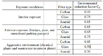
reduced based on the environmental exposure condition. The constituent materials, fibers, and resins of an FRP system affect its durability and resistance to environmental exposure. The environmental reduction factors given in Table 1 are conservative estimates based on the relative durability of each fiber type.
Equations (1) and (2) give the tensile properties that should be used in all design equations. The design ultimate tensile strength should be determined using the environmental reduction factor given in Table 1 for the appropriate fiber type and exposure condition.
*
In the strengthening of RC structures, FRP plates or sheets are externally bonded to RC structures using epoxy resins.
f fu CE f fu
(1)
For the external FRP to be effective in enhancing load- carrying capacity of the structure, effective stress transfer is
Similarly, the design rupture strain should also be reduced
for environmental exposure conditions.
required between FRP and concrete. The code analyses are
based on the fact that the structure and FRP material acts elastically.
*
fu E fu
TABLE 1
(2)
The main purpose of this study is to establish a
comparative study for governing parameters according to the three code guidelines (ACI440.2R-08[1], ISIS
ENVIRONMENTAL REDUCTION FACTOR FOR VARIOUS FRP
SYSTEMS AND EXPOSURE CONDITIONS
CANADA[3] & TR-55[4]). This
comparative study may
include the comparison of conservativeness regarding strength or moment capacity.
The influences of different parameters on the strengthening project have been investigated in this study. The variation of these influential effects with respect to the design guidelines used has also been investigated.
Then the same calculation process is done for 10 identical
beams with a single varying parameter.
For other parameters the same process is done with different spreadsheets for each of the parameters.
2 CODE ANALYSIS
The determination of nominal and ultimate strength for
Because FRP materials are linearly elastic until failure (assumption), their design modulus of elasticity for unidirectional FRP can be determined from Hooke’s law.
different parametric values is
accomplished exactly as
The expression for the modulus of elasticity, given in
specified by the respective code. For this purpose simply
equation (3), recognizes
that the modulus is typically
supported singly reinforced beams have been considered. The strength influencing parameters that have been varied
unaffected by environmental conditions. The modulus given in this equation will be the same as the initial value
are FRP ratio f ; FRP strength f fu ;
FRP strain fu ;
reported by the manufacturer.
modular ratio of FRP material E f .

E f f fu
fu
(3)
2.1 Analysis according to the ACI 440.2R-08
ACI440.2R has been in its latest form since 2008,
Failure modes: The flexural strength of a section depends on
the controlling failure mode. The following flexural failure modes should be investigated for an FRP-strengthened section (GangaRao and Vijay [6]):
superseding the previous 2002 version
with significant
Crushing of the concrete in compression before yielding of
changes. ACI 440.2R-08[1] has been following the stress
distribution diagram of concrete member in bending as per
ACI: 318.
Environmental reduction factor: The material properties
the reinforcing steel;
Yielding of the steel in tension followed by rupture of the
FRP laminate;
Yielding of the steel in tension followed by concrete
reported by manufacturers, such as the
ultimate tensile
crushing;
strength, typically do not consider long-term exposure to
IJSER © 2015 http://www.ijser.org
1327
International Journal of Scientific & Engineering Research, Volume 6, Issue 2, February-2015
ISSN 2229-5518
Shear/tension delamination of the concrete cover (cover
delamination) and
Debonding of the FRP from the concrete substrate (FRP
debonding).
Concrete crushing is assumed to occur if the compressive strain in the concrete reaches its maximum usable strain
( cu = 0.003). Rupture of the externally bonded FRP is
assumed to occur if the strain in the FRP reaches its design
Existing substrate strain: Unless all loads on a member,
including self-weight and any pre-stressing forces, are removed before installation of FRP reinforcement, the substrate to which the FRP is applied will be strained. These strains should be considered as initial strains and should be excluded from the strain in the FRP (Arduini and Nanni[2]; Nanni and Gold [9]). The initial strain level on the bonded substrate, ε , can be determined from an
rupture strain ( f f
f fu ) before the concrete reaches its
elastic analysis of the existing member, considering all
loads that will be on the member during the installation of
maximum usable strain. Cover delamination or FRP
debonding can occur if the force in the FRP cannot be sustained by the substrate. Such behavior is generally
referred to as debonding, regardless of where the failure
the FRP system. The elastic analysis of the existing member should be based on cracked section properties.
M DL (h kd )

bi
plane propagates within the FRP-adhesive substrate region.
Icr Ec
(5)

Away from the section where externally bonded FRP terminates, a failure controlled by FRP debonding may govern. To prevent such an intermediate crack-induced debonding failure mode, the effective strain in FRP reinforcement should be limited to the strain level at which debonding may occur, fd as defined in equation (4)
f '
Strain level in FRP reinforcement: It is important to determine the strain level in the FRP-reinforcement at the ultimate limit state. Because FRP materials are linearly elastic until failure, the level of strain in the FRP will dictate the level of stress developed in the FRP. The maximum strain level that can be achieved in the FRP reinforcement will be governed by either the strain level developed in the FRP at the point
at which concrete crushes, the point at which the FRP
fd 0.83
c 0.9 fu

nt f E f
f '
in in-lb units
ruptures, or the point at which the FRP debonds from the substrate. The effective strain level in the FRP reinforcement at the ultimate limit state can be found from
fd 0.41
c 0.9 fu in SI units (4)
nt f E f
equation (6)
d f c
Assumptions: the following assumptions are made in calculating the flexural resistance of a section strengthened

fe cu (
c
) bi fd
(6)
with an externally applied FRP system:
Design calculations are based on the dimensions, internal
Where, ε is the initial substrate strain and d f
effective depth of FRP reinforcement.
is the
reinforcing steel arrangement, and material properties of the
existing member being strengthened;
The strains in the steel reinforcement and concrete are directly proportional to the distance from the neutral axis. That is, a plane section before loading remains plane after loading;
There is no relative slip between external FRP reinforcement
Stress level in the FRP reinforcement: The effective stress level in the FRP reinforcement is the maximum level of stress that can be developed in the FRP reinforcement before flexural failure of the section. This effective stress level can be found from the strain level in the FRP, assuming perfectly elastic behavior.
and the concrete;
f fe E f fe
(7)
The shear deformation within the adhesive layer is neglected
because the adhesive layer is very thin with slight variations in its thickness;
The maximum usable compressive strain in the concrete is
0.003;
Based on the strain level in the FRP reinforcement, the strain level in the non-prestressed steel reinforcement can be found from equation (8) using strain compatibility

( ) (d c)
The tensile strength of concrete is neglected; and
(d f c)
(8)
The FRP reinforcement has a linearly elastic stress-strain
relationship to failure.
While some of these assumptions are necessary for the sake
The stress in the steel is determined from the strain level in the steel using its stress-strain curve
of computational ease, the assumptions do not accurately
fs Es s f y
(9)
reflect the true fundamental behavior of FRP flexural
reinforcement. For example, there will be shear deformation in the adhesive layer causing relative slip between the FRP and the substrate. The inaccuracy of the assumptions will not, however, significantly affect the computed flexural strength of an FRP-strengthened member. An additional strength reduction factor will conservatively compensate for any such discrepancies.
With the strain and stress level in the FRP and steel reinforcement determined for the assumed neutral axis depth, internal force equilibrium may be checked using equation (10)
IJSER © 2015 http://www.ijser.org
International Journal of Scientific & Engineering Research, Volume 6, Issue 2, February-2015
ISSN 2229-5518
1328
( As fs Af f fe )
c
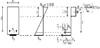
Figure 1: Elastic strain and stress distribution
Environment Reduction Factor: It is not included in this

11
f 'b
(10)
method but the strength reduction factors are high
compared to ACI method and so it is mostly
The terms α and β in equation (10) are the parameters defining a rectangular stress block in the concrete equivalent to the nonlinear distribution of stress. If concrete crushing is the controlling mode of failure (before or after steel yielding), α and β can be taken as the values associated with the Whitney stress block. If FRP rupture, cover delamination, or FRP debonding occur, the Whitney stress block will give reasonably accurate results. A more accurate stress block for the strain level reached in the concrete at the ultimate-limit state may be used.
The depth to the neutral axis c is found by
simultaneously satisfying equation (5-9) thus establishing
compensated.
Strength Reduction Factor or Resistance Factor
TABLE 2: STRENGTH REDUCTION FACTOR
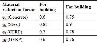
Generally the (carbon) = 0.75 and (glass) = 0.5 is
internal force equilibrium and strain compatibility. To solve for the depth of the neutral axis c, an iterative
frp
considered for the calculation.
frp
solution procedure can be used. An initial value for c is
first assumed and the strains and stresses are calculated
using equation (5-8). A revised value for the depth of neutral axis c is then calculated from equation (9).The calculated and assumed values for c are then compared. If they agree, then the proper value of c is reached. If the calculated and assumed values do not agree, another value for c is selected, and the process is repeated until convergence is attained.
The nominal flexural strength of the section with FRP
external reinforcement is computed from equation (10). An additional reduction factor for FRP f , is applied to the flexural-strength contribution of the FRP reinforcement.The recommended value of f is 0.85.
Assumption: It is assumed that FRPs are perfectly linear-
elastic materials. Thus failure of an FRP strengthened
section in flexure can be due to FRP rupture or concrete
crushing. The ultimate flexural strength for both of these failure modes can be calculated using a similar methodology as that used for steel-reinforced sections. Hence the following additional assumptions are required:
Plane sections remain plane;
Perfect bond exists between concrete and steel reinforcement and between concrete and FRP reinforcement;
Adequate anchorage and development length is ensured
for the FRP reinforcement;
FRPs are linearly elastic to failure;
Concrete compressive stress-strain curve is parabolic and
concrete has no strength in tension;
M A f (d 1c ) A f (d
1c )
Initial strain in the section at the time of strengthening

n s s 2

f f fe f 2
(11)
can, in most cases, be ignored.
In addition steel is treated as elastic-perfectly plastic,
2.2 Analysis according to ISIS Educational
Module 4:
ISIS CANADA has given the guideline for design of externally reinforced /bonded FRP laminated beam .In ISIS code the design strain is not limited up to debonding failure, existing substrate strain not deducted for effective strain of fiber and the strength reduction factor are different than ACI method to find out the strength of beam.
with strain hardening neglected and concrete is treated using the concept of equivalent stress block.
Failure modes: There are four potential flexural failure
modes for externally-strengthened reinforced concrete flexural members:
Concrete crushing before yielding of reinforced steel;
Steel yielding followed by concrete crushing; Steel yielding followed by FRP rupture and
Debonding of the FRP reinforcement at the FRP/concrete interface.
IJSER © 2015 http://www.ijser.org
International Journal of Scientific & Engineering Research, Volume 6, Issue 2, February-2015
ISSN 2229-5518
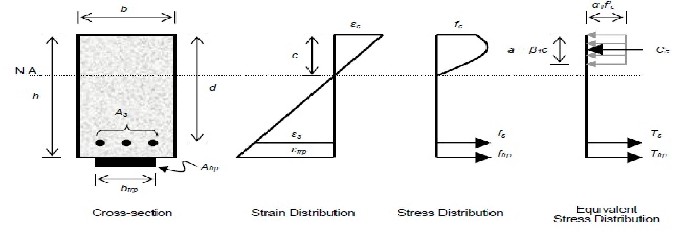
Figure 2: Stress strain profile of a beam strengthened in flexure with externally bonded FRP material.
1329
It is not clear at the outset of a design or analysis which of the above failure modes will govern. Thus an assumption is made and the failure mode is checked.
If the assumption is incorrect, another failure mode is
assumed and the analysis is repeated. In usual cases, it is assumed that the fourth failure mode, FRP debonding, will not occur and can be ignored.
Equilibrium of internal forces requires that three stress
resultants (concrete in compression Cc , steel in tension Ts
, FRP in tension Tfrp ) sum to zero. Thus
cc Ts Tfrp
(12)
The stress resultants can be determined using the
following expressions;
c f 'bc
2.3 Analysis according to The Concrete Society
TR-55
Bonding FRP to the tension face increases the flexural strength of concrete elements. Failure of the element may then occur as a result of various mechanisms, as follows:
Concrete crushing or FRP rupture
FRP separation due to end peel or debonding. Comparison of the design ultimate moment M u , with the balanced moment of resistance M r ,b , predicts the likely mode of failure. The moment M u can be calculated using elastic or plastic methods of analysis, although it is common practice to adopt the former. The balanced
condition is assumed to occur when the concrete and the
Ts s As fs with
fs f y
(13)
FRP reach their ultimate strains simultaneously, as shown
Tfrp frp Afrp E frp frp
with frp frpu
(14)
in Fig. 3. Equation (16), obtained by taking moments
Equation (11) can be used in combination with equation
about the bottom face, can be used to calculate M r ,b .
(12-14) and strain compatibility as illustrated in figure 2 to determine the depth of neutral axis. Thus the moment
M r ,b

0.67 f
cu
f y

0.9bx[ z (h d )]
As (h d )
(16)
capacity can be determined as;
mc ms
M T (d a ) T
(h a ) where a c
(15)

n s 2

frp 2 1
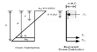
Figure 3: Assumed strain distribution at failure.
Figure 4: Stress and strain distributions at balanced condition.
If M u M r ,b , failure occurs due to concrete crushing and the area of FRP can be determined using standard stress- strain curves for concrete and steel reinforcement by assuming that the FRP reinforcement has a straight line response to failure as shown in Figure 4. The area of FRP is estimated using the following expression
Ff

Af
f
(17)
IJSER © 2015 http://www.ijser.org
1330
International Journal of Scientific & Engineering Research, Volume 6, Issue 2, February-2015
ISSN 2229-5518
Where Ff is the tensile force in the FRP, and f is the stress in the FRP given by
3 RESULTS AND DISCUSSION
For the final step of the comparative study, the obtained
f f E fd (cft cit )

E
(18)
capacities for 10 beam specimens for various parameters
according to the 3 codes under this study are plotted in
In which E fd
f
mE
is the elastic modulus of FRP, cft is
plain graphs. Every parameter has its own graphical
representations. Since each graph contains 3 plotted curves
the final tensile strain in the concrete at the FRP/concrete interface, and cit is the initial tensile strain in the concrete at the FRP/concrete interface calculated on the basis of an elastic analysis of the cracked section.
for 3 Codes, the variations of the 3 Codes have been shown through these graphs.
Parametric Study

Af
If M u M r ,b , failure theoretically occurs due to FRP
Case I. FRP Reinforcement Ratio ( f
bd )
rupture. However, laboratory tests show that FRP rupture is a rare event and plate separation due to debonding is more likely. The critical value of strain is used to calculate the design stress in the FRP.
Figure 5 shows the variation of flexural moment capacity
for the changes in FRP application ratio.
1000
800
600
400
200
0
0 0.0005 0.001 0.0015 0.002
FRP ratio (ρf)
ACI ISIS TR-55
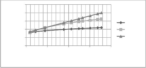
Figure 5 Moment Capacity versus FRP Ratio
It shows that the range of FRP reinforcement ratio
f is
Case II. FRP Modular Ratio E f
(Gpa)
within 0.2% to 2.5% and thus obtained moment capacities
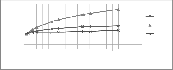
Figure 6 shows the variation of moment capacity with
vary widely. For small
f the change in capacities for the
changes in FRP modular ratio E f .
three codes are not significant, but for larger f
ratios the
It shows that TR-55 predicts the lowest capacity than ACI
capacity difference is wide. It shows that ACI 440 code
provide the more conservative result and TR-55 the least.
Under the same conditions ( s 0.4% , f y 415Mpa ,
440 and ISIS. Hence TR-55 is more conservative in the context of E f . ACI prediction goes next to it. ISIS shows the
least conservativeness for FRP modular ratio E f .
fc 30Mpa , f fu 2800Mpa ,
E f 165Gpa ) ISIS dictates
The range of E f
has been taken from 13 Gpa to 640 Gpa.
failure by concrete crushing after f crosses 0.0089%, while
all other codes determine failure by FRP rupture. Canadian
At the smaller values of E f
the differences in capacities for
code imposes strong F.S (Concrete Compressive Stress
the three codes are small. With the increase in
E f the
Block Factor
1 and Concrete Compressive Stress Block
change of capacities for the codes varies widely.
Factor 1 ) on concrete compressive strength
fc more than
the other codes resulting in failure by concrete crushing abundant.
IJSER © 2015 http://www.ijser.org
1331
International Journal of Scientific & Engineering Research, Volume 6, Issue 2, February-2015
ISSN 2229-5518
900
800
700
600
500
400
300
200
100
0
0 200 400 600 800
Ef (Gpa)
ACI ISIS TR55
Figure 6: Moment Capacity versus FRP Modular Ratio
800
700
600
500
400
300
200
100
0
0 1000 2000 3000 4000 5000
ACI ISIS TR55
* (Mpa)
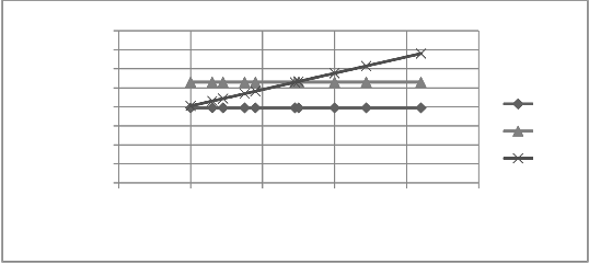
Figure 7: Moment Capacity versus FRP Ultimate Strength
Case III. FRP Ultimate Strength
* (Mpa)
The variation of flexural moment capacity for the changes of FRP ultimate strength from 1000 Mpa to 4200 Mpa has been shown in figure 7.
It shows a clear distinction among the three codes; ACI 440, ISIS and TR-55. ACI and ISIS have a straight line which means that moment capacities are independent of FRP
ultimate strength f * . This type of graphs might have resulted from the fact that both the codes follow strain
compatibility method. Hence the analysis procedures do
not employ FRP ultimate strength. Both of these codes use f * to limit the stress condition as a limiting value for the determination of failure condition. On the other hand TR-
55 involves both stress and strain compatibility (Eq.3-18)
resulting in a steep sloped straight line. Hence the flexural capacity increases steadily with f * . From the aspect of conservativeness ACI is most conservative and ISIS and
TR-55s conservativeness are next to it.
4 CONCLUSIONS
From the detailed study of the three widely recognized codes (ACI 440, ISIS and TR-55) it can be said that most of the parameters studied have beneficiary influence on moment capacity. These influences of the parameters largely depend on the analysis procedure and the assumptions behind these analyses. Hence the effects of some parameters can be used in a beneficiary way for an old and failing beams retrofitting while others cannot be. From the study in this research work the following conclusions can be drawn:
Application of FRP at the tension side generally increases flexural moment capacity of a beam. Increase in FRP application ratio, f increases moment capacity
significantly. In this context, ACI 440 shows quite conservativeness than ISIS and TR-55.
IJSER © 2015 http://www.ijser.org
1332
International Journal of Scientific & Engineering Research, Volume 6, Issue 2, February-2015
ISSN 2229-5518
The modular ratio
E f acts also congenially for the
[10] MacDonald, M.D., and Calder, A.J.J. (1982), “Bonded Steel Plating
retrofitting. Hence if a FRP sheet has a higher modulus
of elasticity it will add to the moment capacity upon application externally than a FRP sheet with lower modulus of elasticity. Though, TR-55 show less dependency on it and ISIS shows the most influence.
for Strengthening Concrete Structures” International of Journal of
Adhes, vol.2 (2), pp.119-127.
[11] Meier, U. (1992), “Carbon Fiber-Reinforced Polymers: Modern Materials in Bridge Engineering,” Structural Engineering International, Vol. 2, No. 1, pp.7-12.
FRP ultimate strength
f * which is provided by the
[12] Oehlers, D. J., and Moran, J. P., “Premature Failure of Externally
manufacturer has significance in retrofitting if the
design is made following British Standard (TR-55). The other codes depend on it only to limit the stress developed in FRP.
Design procedures and the guidelines followed play an
important role in the resulting capacity which can be verified through practical experimentations.
The surrounding environmental condition affects the resulting moment capacity. Hence the analytical result may vary with the practical capacity depending on the type of region the structure is located.
REFERENCES
[1] ACI 440 2R-(2008) “Guide for the design and construction of externally bonded FRP system for strengthening concrete structures.” ACI committee, Farmington Hills, U.S.A. pp 21-29.
[2] Arduini, M., Nanni, A., Di Tommaso, A., and Focacci, F. (1997), “Shear Response of Continuous RC Beams Strengthened with Carbon FRP Sheets,” Proceeding of the Third International Symposium on Non-Metallic (FRP) Reinforcement for Concrete Structures (FRPRCS-3), Japan Concrete Institute, Sapporo, Japan, vol. 1, pp. 459-466.
[3] Bhunga, Murad M. and Arora, N.K.(2012). “Comparative Study of ER-FRP Laminated Beam Design with ACI 440.2R-08 and ISIS CANADA method.” International Journal of Advanced Engineering Research and Studies.
[4] Concrete Society-TR55,(2004) “Design guidance for strengthening concrete structures using fiber composite materials.”, The Concrete Society, Camberley, UK, Technical Report No. 55 (2/e).
[5] Ganga Rao, H. V. S., and Vijay, P. V., 1997b, “Aging of Structural Composites under Varying Environmental Conditions,” Proceedings of the Third International Symposium on Non- Metallic (FRP) Reinforcement for Concrete Structures (FRPRCS-
3), vol 2, Japan Concrete Institute, Tokyo, Japan, pp. 91-98.
[6] GangaRao, H. V. S., and Vijay, P. V., 1997a, “Design of Concrete Members Reinforced with GFRP Bars,” Proceedings of the Third International Symposium on NonMetallic (FRP) Reinforcement for Concrete Structures (FRPRCS-3), vol 1, Japan Concrete Institute, Tokyo, Japan, pp. 143-150.
[7] Hankers, C. and Rostasy, F.S. (1997), “Verbundtragverhalten laschenverstarker Betonbautele unter schwellender Ver- bundbeanspruchung”, Beton und Stahlbetonbau 92: pp.19-23.
[8] Hussain, M., Sharif, A., Basunbul, I. A., Baluch, M. H., and Al- Sulaimani, G. J. (1995), “Flexural Behavior of Precracked Reinforced Concrete Beams Strengthened Externally by Steel Plates,” ACI Structural Journal, vol. 92, No. 1, pp. 14-22.
[9] Khalifa, A., Gold, W., Nanni, A., and Abdel -Aziz M. I. (1998) "Contribution of Externally Bonded FRP to the Shear Capacity of RC Flexural Members" Journal of Composites for Construction - ASCE, vol. 2, No. 4, pp. 195-202.
Plated Reinforced Concrete Beams,” ASCE Journal of Structural
Engineering, vol. 116, NO. 4, pp.978-995, April.
[13] Swamy, R. N., Jones, R., and Charif, A. (1989), “The Effect of External Plate Reinforcement on the Strengthening of Structurally Damaged RC Beams,” The Structural Engineer, vol. 67, No. 3, pp.
45-54.
[14] Swamy, R. N., Jones, R., and Bloxam, J. W. (1987), “Structural Behavior of Reinforced Concrete Beams Strengthened by Epoxy- Bonded Steel Plates,” The Structural Engineer, vol. 65A, No. 2, pp.
59-68.
[15] Rutz, H.G. and Cimino, T.M. (1995), “Advanced Properties of High Density Ferrous Powder Metallurgy Materials, Advances in Powder Metallurgy and Particulate Materials,” vol 3, Part 10, Metal Powders Induslries Federation, , p 97-117.
[16] Van Gemert, D., and Maesschalck, R., “Structural Repair of a Reinforced Concrete Plate by Epoxy Bonded External Reinforcement,” The International Journal of Cement Composites and Lightweight Concrete, vol. 5, No. 4, pp. 247-255, November
1983.
————————————————
Tanni Alam Dola, department of civil engineering, Bangladesh University of Engineering and Technology, Bangladesh, E-mail: tanni.alam.2014@gmail.com
Md. Zakaria Ahmed is currently teaching as professor in civil engineering department of Bangladesh University of Engineering and Technology, Bangladesh, E-mail: mzahmed@ce.buet.ac.bd
IJSER © 2015 http://www.ijser.org